background image

The Technical Stuff 

__________________________________________________________


- 25 -


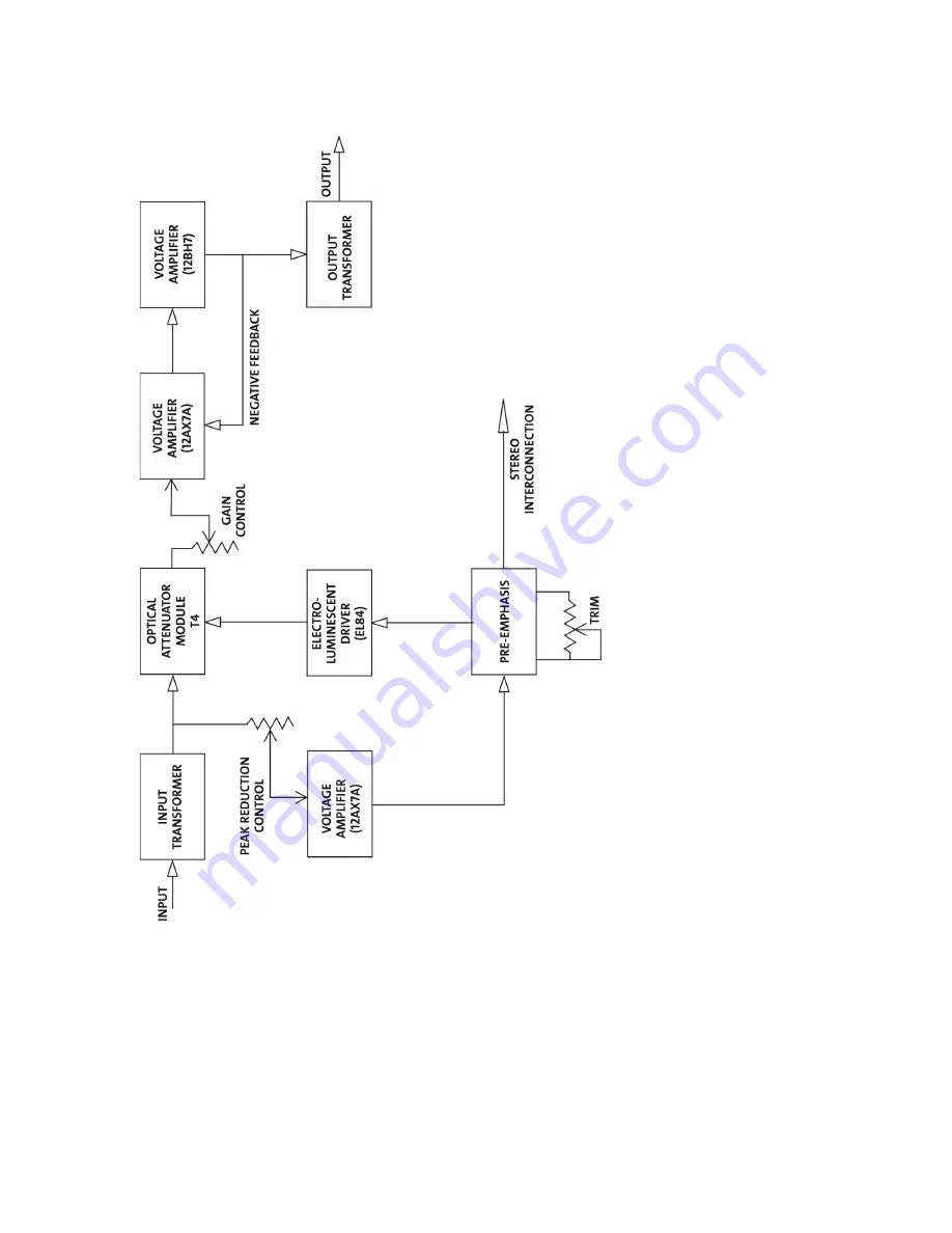
Block Diagram 


As shown in the illustration above, each channel’s input transformer provides isolation and impedance 
matching. After this, the signal is fed into both the side-chain circuit and the gain reduction circuit. 
The side-chain is comprised of a voltage amplifier, a pre-emphasis filter, and a driver stage which 
provides the voltage necessary to drive the electro-luminescent panel. This signal controls the gain of 
the compressor. After the gain reduction circuit, the signal is sent through an output Gain control and 
a two-stage output amplifier, followed by the output transformer. 


Summary of Contents for 2-LA-2

Page 1: ...Model 2 LA 2 Twin T4 Leveling Amplifier Universal Audio Part Number 65 00035 Universal Audio Inc Customer Service Tech Support 1 877 MY AUDIO Business Sales Marketing 1 866 UAD 1176 www uaudio com ...

Page 2: ... artwork product designs and design concepts are subject to copyright protection No part of this document may be reproduced in any form without prior written permission of Universal Audio Inc Trademarks 2 LA 2 LA 2A LA 3A LA 610 1176LN 2 1176 6176 2 610 710 4110 8110 SOLO 2A SOLO 110 SOLO 610 2192 DCS Remote Preamp UAD and the Universal Audio Inc logo are trademarks of Universal Audio Inc Other co...

Page 3: ...nk the 2 LA 2 provides matched T4s for stereo operation while retaining the core sonic signature components in order to deliver the same trademark sound of the LA 2A long treasured by engineers worldwide From drum bus to master bus vocals to vibraphones the 2 LA 2 delivers the same authentic smooth as silk gain reduction you ve come to know and trust with the LA 2A conveniently reconfigured into a...

Page 4: ...the plug body when connecting or disconnecting it 7 Grounding of the Plug This unit is equipped with a 3 wire grounding type plug a plug having a third grounding pin This plug will only fit into a grounding type power outlet This is a safety feature If you are unable to insert the plug into the outlet contact your electrician to replace your obsolete outlet Do not defeat the purpose of the groundi...

Page 5: ...nical Stuff History of the 2 LA 2 Compressor Basics Electro Optical Compression Limiting Operating The 2 LA 2 In Link Mode Making A Custom Insert Cable Maintenance Information Meter Calibration Changing the Internal Voltage Selector Changing Fuses Block Diagram Glossary of Terms Recall Sheet Specifications Additional Resources Product Registration Warranty Service Support Inside back cover i ii 2 ...

Page 6: ...ed and place it there The 2 LA 2 is housed in a standard two rackspace 19 chassis and so we recommend that it be securely mounted in a rack if possible Step 2 Make sure the Power switch in the center of the front panel is off down and then connect the supplied IEC power cable to the rear panel AC power connector Step 3 Set the LINK DUAL switch in the center of the front panel to its down DUAL posi...

Page 7: ...ated turn the Gain knob clockwise to make up the difference Set the Meter switch back to its down OUTPUT position in order to view the final output level of the left channel of the 2 LA 2 and ensure that you are applying the correct amount of makeup gain Step 8 Set the left channel LIMIT COMPRESS switch to its up LIMIT position in order to hear the effect of the 2 LA 2 in limiting mode where a hig...

Page 8: ...n reduction When OUTPUT is selected the down position a meter reading of 0 corresponds to a level of 4 dBm at the rear panel line output When GR Gain Reduction is selected the up position the channel s meter will read 0 dB when there is no incoming signal or when no compression is being applied 4 Gain Determines the final output level of the 2 LA 2 channel A setting of approximately 6 is unity gai...

Page 9: ...y on one channel see page 20 for more information 8 Power Turns the 2 LA 2 power on or off When powered on the purple LED immediately above the switch lights up 9 BYPASS COMP switch Allows the gain reduction circuit to be placed in or out of the audio path This is useful in comparing the compressed signal to the non compressed signal with the flip of a switch This is also useful if the user wishes...

Page 10: ...e delay slow blow fuse for operation at 240 volts 2 LINE OUTPUT A balanced XLR connector carrying the line level output signal of the 2 LA 2 channel This signal will normally be routed via a patchbay to a channel or bus insert return 3 LINE INPUT Connect line level input signal for each channel to this balanced XLR connector Pin 2 is wired positive hot This signal will normally be arriving via a p...

Page 11: ...___________________ 7 Figure 3 Using the 2 LA 2 as a send return processor In the above illustration one side of the 2 LA 2 is used as a send return processor Typically a specialized send return cable is used for this purpose see page 21 for more information ...

Page 12: ..._________________ 8 Figure 4 using the 2 LA 2 inline with a mic preamp In the above illustration one side of the 2 LA 2 is used inline with a mic preamp This is typically done to prevent peaks in the input signal from overdriving the recording device or mixer ...

Page 13: ...cs But according to Cooper the LA 2A made it easy providing completely transparent gain reduction and a velvety tone The result was a vocal track that sounded dramatically smoother and warmer And he notes it took well under a minute to dial in the sound His conclusion The LA 2A s uniquely transparent processing makes it incredibly effective for treating vocals When you need to warm up a piercing o...

Page 14: ...se For a mix of a pop rock track in Pro Tools using the LA 2A inserted on electric guitar was even more of a no brainer if you often compress electric guitars buy an LA 2A and you can thank me later Ace engineer Jim Scott Tom Petty Red Hot Chili Peppers Wilco says I use LA 2As all the time I use them on bass and it s one of the compressors I use for reverb Often I ll send a bunch of things to one ...

Page 15: ...ish with a broad but gentle low end boost Ducking Applications When the 2 LA 2 is placed in stereo Link mode the Peak Reduction knobs in each channel serve to mix the two incoming signals to the side chain circuit of both channels In most musical applications you will want the left and right signals to affect the compressor equally so that a transient occurring in one channel will serve to increas...

Page 16: ...f which around one hundred units were made Teletronix LA 1 At the heart of the LA 1 was an electro optical sensor This was a small light proof metal canister which housed two components a photoelectric cell a light sensitive device whose electrical resistance changes depending upon the intensity of light to which it is subjected typically used in the home to sense when darkness falls and then swit...

Page 17: ...ts that are still in regular use decades after their development In 2000 Bill Putnam Sr was awarded a Technical Grammy for his multiple contributions to the recording industry Highly regarded as a recording engineer studio designer operator and inventor Putnam was considered a favorite of musical icons Frank Sinatra Nat King Cole Ray Charles Duke Ellington Ella Fitzgerald and many many more The st...

Page 18: ...en by its historical roots and a desire to wed classic analog technology with the demands of the modern digital studio Compressor Basics The function of a compressor is to automatically reduce the level of peaks in an audio signal so that the overall dynamic range that is the difference between the loudest sections and the softest ones is reduced or compressed thus making it easier to hear every n...

Page 19: ...or in compression is the level of the input signal Large loud input signals result in more gain reduction while smaller softer input signals result in less gain reduction Threshold is another important factor It is a term used to describe the level at which a compressor starts to work Below the threshold point the volume of a signal is unchanged above it the volume is reduced For example if a comp...

Page 20: ...cks in that is any change in input no matter how great results in virtually no increase in output level Infinity 1 is the ratio used by the 2 LA 2 when a channel is operating in limiting mode that is when its front panel switch is set to LIMIT however the 2 LA 2 is designed so that the same warm sonic characteristics are retained even though more severe gain reduction is applied As an aside an exp...

Page 21: ...ain is restored If the release time is too long however a loud section of the program may cause gain reduction that persists through a soft section making the soft section inaudible The 2 LA 2 is unique in that it provides a dual stage release time in the first 60 milliseconds approximately half the signal is released with the remainder taking anywhere from 1 second to 15 seconds to die away depen...

Page 22: ...to exacting specs that were originally found on the LA 2A No other manufacturers have access to these cells The genius of the el op circuit lies in its simplicity the larger the signal that is applied to the EL panel the brighter the light that is generated the brighter the light the less resistance the photo cell which controls the gain of the electrical circuit exhibits Thus the louder the incom...

Page 23: ...amount of time it takes for the photo cell to recover after the light is removed depends on how long light had been shining on it and how bright the light was This causes something called memory effect As a result you can actually train the T4 s response characteristics by pre rolling material for a minute or two essentially saturating the photo cell Similarly because the amount of time it takes t...

Page 24: ...ly 2 In the left channel of the 2 LA 2 only set the Limit Compress switch as desired and adjust the Peak Reduction and Gain knobs until the desired amount of compression or limiting is heard 3 In the right channel of the 2 LA 2 set the Limit Compress switch and the Peak Reduction and Gain knobs of the right channel to the identical setting as the left channel and then begin monitoring both channel...

Page 25: ...le XLR cable connector 1 Male XLR cable connector 1 1 4 TRS cable connector A suitable length of light gauge unbalanced microphone cable A short piece of 22 gauge bus wire Then follow these steps to assemble the cable 1 Cut two lengths of audio cable suitable to reach from the 2 LA 2 to the insert point on your mixer Light gauge cable should be used in order to allow the two cables to comfortably ...

Page 26: ...__________________________________________________________ 22 5 Your finished cable should look like the photograph below Be sure to check continuity with a voltmeter or test light before use to ensure proper grounding and signal flow ...

Page 27: ...sure there is no signal present 4 Use a small screwdriver to slowly adjust the GR Zero Set potentiometer so that the meter reads 0 dB Watch how the meter settles before completing the calibration Changing the Internal Voltage Selector The 2 LA 2 can operate at 100V for use in Japan 120V or 240V To change the internal voltage selector wait 5 minutes after power down then unplug the AC power cord fr...

Page 28: ...your area before applying AC power to the unit Failure to do so may damage the unit Changing Fuses The AC power fuse is located in the AC power connector block Remove the power cord before checking or changing the fuse A 1 6 A time delay slow blow fuse is required for operation at 100 or 120 V A 800 mA time delay slow blow fuse is required for operation at 240 V Never substitute different fuses ot...

Page 29: ...ed into both the side chain circuit and the gain reduction circuit The side chain is comprised of a voltage amplifier a pre emphasis filter and a driver stage which provides the voltage necessary to drive the electro luminescent panel This signal controls the gain of the compressor After the gain reduction circuit the signal is sent through an output Gain control and a two stage output amplifier f...

Page 30: ... harsh form of audio distortion caused when the loudness of an incoming signal exceeds an audio recording device s capability to represent its amplitude When that happens the peaks of the signal simply get clipped off thus drastically changing the waveform When clipping occurs in a digital recording device the result is an especially unpleasant sound Compression The process of automatically reduci...

Page 31: ...turn The jack is wired with a normalled connection so that with nothing plugged in the send and return are connected together Knee A term used to describe whether a compressor will reach maximum gain reduction quickly or slowly A gradual transition is called soft knee while a more rapid transition is called hard knee The 2 LA 2 utilizes soft knee compression and limiting which is generally more de...

Page 32: ...ng and breathing artifacts can occur due to the rapid rise of background noise as the gain is restored If the release time is too long however a loud section of the program may cause gain reduction that persists through a soft section making the soft section inaudible The 2 LA 2 features a dual stage release where it takes approximately 60 milliseconds for the first 50 of release then from 1 to 15...

Page 33: ...Recall Sheet __________________________________________________________ 29 ...

Page 34: ...ogram dependent Attack Time 10 ms program dependent Release Time Dual stage 60 ms for 50 release then 1 15 seconds program dependent Signal To Noise 70 dBu Distortion 0 35 at 10 dBm 0 75 at 16 dBm Meter Gain Reduction dB and Output dB Input Output Connections XLR Tube Complement 2 12AX7 1 12BH7 1 EL84 per channel Power Connector Detachable IEC power cable Power Requirements 100 V 120 V 240 V Fuse ...

Page 35: ...here at UA is to get you up and running again as soon as possible The first thing to do if you re having trouble with your device is to check for any loose or faulty external cables bad patchbay connections grounding trouble from a power strip and all inputs outputs mic line Hi Z etc If your problem persists call tech support at 877 MY UAUDIO or send an email to hardwaresupport uaudio com and we w...

Reviews: