Page 18 of 44
Page 19 of 44
MAN.500.REVD.06302015
Start-Up
Apply power to the Universal Analyzers 500 Series Thermoelectric Gas Cooler. The indicated temperature will start to
drop immediately. It should be below the over-temperature set point in approximately four minutes and the “COOL” green
LED lamp should light. When the temperature reaches the control point (set at 5
°
C), the rate at which the temperature
drops will be reduced. It will stabilize between 4
°
and 5
°
C.
Start the sample gas flow. Water should be observed to be removed from the bottom of the heat exchanger when steady
state conditions are established.
If moisture sensors are installed, the (DRY) light should remain on as dry gas is transported to the analyzer(s). Turn on the
analyzer(s) and calibrate as required.
Shutdown
Stop sample gas flow to the Universal Analyzers 500 Series Thermoelectric Gas Cooler by turning off the sample pump.
Allow the drain pump to run for several minutes to remove any remaining condensate from the heat exchangers. After all
condensate has been drained, turn off power to the cooler.
Summary of Contents for 500 series
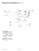
Page 12: ...Page 12 of 44 MAN 500 REVD 06302015 Electrical Connections Model 520 ...
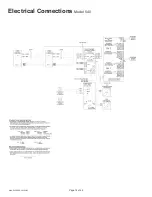
Page 13: ...Page 13 of 44 MAN 500 REVD 06302015 Electrical Connections Model 530 ...
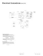
Page 14: ...Page 14 of 44 MAN 500 REVD 06302015 Electrical Connections Model 540 ...
Page 15: ...Page 15 of 44 MAN 500 REVD 06302015 Electrical Connections Model 560 ...
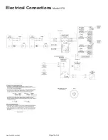
Page 16: ...Page 16 of 44 MAN 500 REVD 06302015 Electrical Connections Model 570 ...
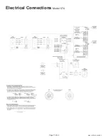
Page 17: ...Page 17 of 44 MAN 500 REVD 06302015 Electrical Connections Model 574 ...
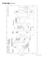
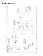
Page 23: ...Page 23 of 44 MAN 500 REVD 06302015 Drawings Model 520 ...
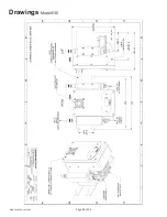
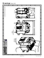
Page 24: ...Page 24 of 44 MAN 500 REVD 06302015 Drawings Model 530 ...
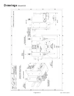
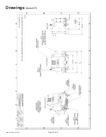
Page 25: ...Page 25 of 44 MAN 500 REVD 06302015 Drawings Model 540 ...
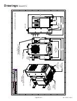
Page 26: ...Page 26 of 44 MAN 500 REVD 06302015 Drawings Model 560 ...
Page 28: ...Page 28 of 44 MAN 500 REVD 06302015 Drawings Model 570 ...

