background image

Page 14 of 44

Page 15 of 44

MAN.500.REVD.06302015

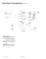
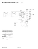
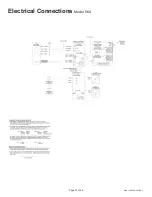
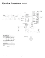
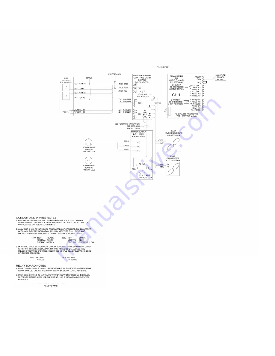
Electrical Connections 

Model 560

Summary of Contents for 500 series

Page 1: ...00 REVD 06302015 Instruction Manual 500 Series Thermoelectric Gas Coolers Units sold prior to 07 01 2015 5200 Convair Drive Carson City NV 89706 Phone 775 883 2500 Fax 775 883 6388 www universalanalyzers com ...

Page 2: ...ymbols 5 Specifications 6 Description and Principle of Operation 8 Installation 11 Electrical Connections 12 Start Up 18 Shutdown 18 Maintenance 19 Troubleshooting 20 Spare Parts 22 Drawings 23 Model 520 23 Model 530 24 Model 540 25 Model 560 26 Model 565 27 Model 570 28 Model 574 29 ...

Page 3: ... 574 31 Relay Board for Models 520 530 560 565 32 Relay Board for Models 540 570 574 33 Drawings Heat Exchangers 34 Metallic Heat Exchangers Temperature Sensing All Models 34 Metallic Heat Exchangers Non Temperature Sensing All Models 36 Glass Kynar Temperature Sensing All Models 38 Glass Kynar Non Temperature Sensing All Models 40 Limited Warranty 42 ...

Page 4: ...refully inspect the product and included accessories immediately on arrival by removing them from the packing and checking for missing articles against the packing list Check the items for any damage which may have occurred during transit and immediately inform the shipping insurance company of any damage found Refer to the Specifications section page 6 for information regarding storage requiremen...

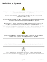
Page 5: ...ON PROVIDED BY THE EQUIPMENT MAY BE IMPAIRED PER CLAUSE 5 4 4 i IN STANDARD EN 61010 1 CAUTION RISK OF DANGER SYMBOL INDICATES INJURY MAY OCCUR IF MANUFACTURER S INSTRUCTIONS ARE NOT ADHERED TO PLEASE READ MANUAL CAREFULLY WHEN SYMBOL IS DISPLAYED CAUTION HOT SURFACE SYMBOL INDICATES EXPOSED SURFACE TEMPERATURE CAN CAUSE BURNS OR PERSONAL INJURY CARE SHOULD BE TAKEN WHEN CONTACT IS REQUIRED CAUTIO...

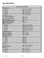
Page 6: ...mum Cooling Power Model 520 63 BTUs per hour 60 kJ hr Model 530 63 BTUs per hour 60 kJ hr Model 540 126 BTUs per hour 120 kJ hr Model 560 126 BTUs per hour 120 kJ hr Model 570 126 BTUs per hour 120 kJ hr Model 574 126 BTUs per hour 120 kJ hr Outlet Sample Dew Point 41 F 5 C Gas Sample Inlet Fitting 3 8 tubing fitting Gas Sample Outlet Fitting 1 4 tubing fitting Bottom Water Drain Fitting 3 8 tubin...

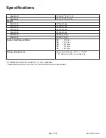
Page 7: ... 5 kg Model 560 21 lbs 9 5 kg Model 570 25 lbs 11 5 kg Model 574 25 lbs 11 5 kg Soluble Gas Removal Rates NO 0 loss NO2 10 loss SO2 2 loss CO 0 loss CO2 2 loss Storage Requirements Cool and dry location 20 F x 120 F 95 relative humidity non condensing AT REDUCED FLOW RATE ABOVE 77 F 25 C AMBIENT DIMENSIONS DO NOT INCLUDE FITTINGS OR MOUNTING HARDWARE Specifications ...

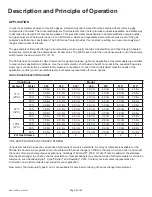
Page 8: ... SELECTION CHART Conditions Model Ambient Water 520 530 540 560 570 574 574 77 F 25 C 12 2 5 l m 4 0 l m 2 5 l m 5 0 l m 4 0 l m 5 0 l m 2 5 l m 15 2 0 l m 4 0 l m 2 0 l m 4 0 l m 4 0 l m 4 0 l m 2 0 l m 30 1 0 l m 4 0 l m 1 0 l m 2 0 l m 4 0 l m 2 0 l m 1 0 l m 50 0 6 l m 4 0 l m 0 6 l m 1 0 l m 4 0 l m 1 0 l m 0 6 l m 90 F 32 C 12 2 0 l m 3 0 l m 2 0 l m 4 0 l m 3 0 l m 4 0 l m 2 0 l m 15 1 8 l ...

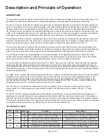
Page 9: ... is a green LED which indicates when the operating temperature has fallen below the factory set temperature of 10 C An Over temperature relay is energized and closed to the cool position when the COOL lamp is on The relay board within the enclosure has dual terminal strip relay contacts for alarm shutdown purposes The external gas sample pump may be interlocked with this relay to power off when te...

Page 10: ...m should be available and visible to the operator This may be accomplished through the use of pressure regulators with gauges flowmeters and or flow control needle valves Condensate removal from the heat exchanger s within the Sample Cooler can be accomplished through one of the following methods 1 A continuously running peristaltic tubing pump 2 Installing the heat exchanger as a bypass condenser...

Page 11: ...o an appropriate condensate disposal location A sample pump is normally required to pull the gas sample through the cooler A Water Carry Over Filter WCOF sensor is recommended for each sample path The pump should be located between the cooler and the filter A clear glass bowl should be installed around the filter to allow checking of the condition of the filter while online Each cooler consumes ab...

Page 12: ...Page 12 of 44 MAN 500 REVD 06302015 Electrical Connections Model 520 ...

Page 13: ...Page 13 of 44 MAN 500 REVD 06302015 Electrical Connections Model 530 ...

Page 14: ...Page 14 of 44 MAN 500 REVD 06302015 Electrical Connections Model 540 ...

Page 15: ...Page 15 of 44 MAN 500 REVD 06302015 Electrical Connections Model 560 ...

Page 16: ...Page 16 of 44 MAN 500 REVD 06302015 Electrical Connections Model 570 ...

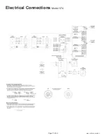
Page 17: ...Page 17 of 44 MAN 500 REVD 06302015 Electrical Connections Model 574 ...

Page 18: ...lize between 4 and 5 C Start the sample gas flow Water should be observed to be removed from the bottom of the heat exchanger when steady state conditions are established If moisture sensors are installed the DRY light should remain on as dry gas is transported to the analyzer s Turn on the analyzer s and calibrate as required Shutdown Stop sample gas flow to the Universal Analyzers 500 Series The...

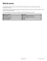
Page 19: ...esigned for maintenance free operation but if any is required ensure power has been removed before maintenance is performed For the best performance of the cooler the following maintenance schedule is recommended Maintenance Activity Frequency Peristaltic pump Replace tubing every 3 months Diaphragm sample pump Replace diaphragm every 6 months Clean heat exchanger Annually Inspect heat sink fins M...

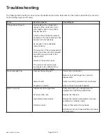
Page 20: ...ube has dropped below 60 psig at the inlet of the thermal valve Failure of the sample cooler The cooler is not cold enough and needs to be calibrated See calibration procedure below No sample gas flow Heat exchanger plugged Alarm shutoff No power on cooler Check for an obstruction Remove heat exchanger from unit and disassemble Verify Cool Dry Indicators are illuminated Ensure cooler has power sup...

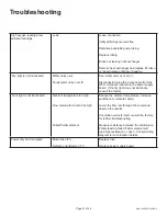
Page 21: ...ed on the power supply board If the dry light does not illuminate consult the factory Cool light is not illuminated Ambient temperature too high Flow rate water content too high Failed Peltier element Reduce the ambient temperature Increase ventilation or relocate cooler Lower the flow rate through the cooler and observe the results If condition corrects itself consult the factory for further trou...

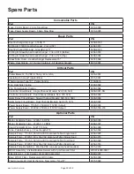
Page 22: ...Channel Models 540 570 575 3600 0002 Alarm Relay Circuit Board Single Channel Models 520 530 560 3600 0006 Alarm Relay Circuit Board Dual Channel Models 540 570 575 3600 0007 Power Supply Board 115VAC 250 Watt 15VDC Output 3600 0038 Power Supply Board 230VAC 250 Watt 15VDC Output 3600 0038 230 Spare Parts Optional Parts Part P N Motor Peristaltic Pump 120VAC 6 RPM 4958 0003 Motor Peristaltic Pump ...

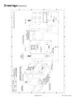
Page 23: ...Page 23 of 44 MAN 500 REVD 06302015 Drawings Model 520 ...

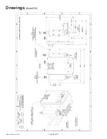
Page 24: ...Page 24 of 44 MAN 500 REVD 06302015 Drawings Model 530 ...

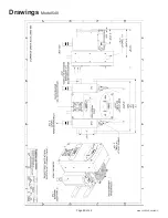
Page 25: ...Page 25 of 44 MAN 500 REVD 06302015 Drawings Model 540 ...

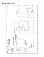
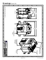
Page 26: ...Page 26 of 44 MAN 500 REVD 06302015 Drawings Model 560 ...

Page 27: ...VERSAL ANALYZERS INC 5200 Convair Driv e Carson City Nevada 89706 USA P1480 06 08 2009 MODEL 565 SAMPLE COOLER M Jenkins 1 2 CONDUIT PORT SINGLE CHANNEL CONTROLLER POWER SUPPLY ENCLOSURE COOLING FAN UPWARD FLOW 5 INSULATED IMPINGER SAMPLE OUTLET 1 4 TUBE CONDENSATE DRAIN 3 8 NPTF 3 TYP SEE SHEET 2 FOR WIRING SCHEMATIC B 02 24 12 Removed AMP Connector MW RW SAMPLE INLET 3 8 TUBE 1 4 1 3 8 6 13 16 9...

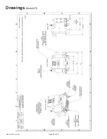
Page 28: ...Page 28 of 44 MAN 500 REVD 06302015 Drawings Model 570 ...

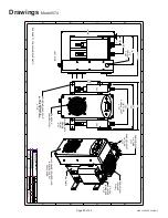
Page 29: ...INGERS 2 TYP HEATSINK DUAL CHANNEL CONTROLLER POWER SUPPLY ENCLOSURE 1 2 CONDUIT PORT 2 3 8 4 7 8 14 3 8 A B C D A B C 1 2 3 4 5 6 7 8 1 2 3 4 5 6 7 D 8 P0290 07 06 1998 N A REV REVISIONS FOR PART NO E Musselman APVD BY DRAWN BY DRAWING NO DATE NOT ISSUED MODEL 574 SAMPLE COOLER ARRANGEMENT DATE DESCRIPTION DWN APVD SCALE SIZE SHEET NTS D 1 OF 2 UNIVERSAL ANALYZERS INC 5200 Convair Driv e Carson C...

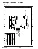
Page 30: ... SET ALARM RELAY SET S2 YELLOW RED GREEN THERMOCOUPLE INPUT CONTROL TEMP SET POINT ALARM RELAY SET POINT CALIBRATE SPAN CALIBRATE ZERO FAN FAN TB1 TB6 R29 R44 R41 R37 FUSE SLOW BLOW 2 AMP P 3 P 4 P2 P1 P4 P3 P2 P1 DC POWER INPUT Carson City Nevada 89706 USA 1701 S Sutro Terrace UNIVERSAL ANALYZERS INC SINGLE CHANNEL SAMPLE COOLERS SHEET SIZE SCALE DATE B DRAWING NO DRAWN BY APVD BY HARVEY MITCHELL...

Page 31: ...RO CALIBRATE SPAN ALARM RELAY SET POINT CONTROL TEMP SET POINT THERMOCOUPLE INPUT CHANNEL 1 CHANNEL 2 2 1 3 4 R44 R37 6 1 2 3 4 5 7 8 A B C D 1 2 3 4 5 6 7 A B C D 8 CONTROL BOARD DUAL CHANNEL SAMPLE COOLERS P0024 07 29 92 1 OF 1 1 1 INSTRUMENT APVD DWN DESCRIPTION DATE REV REVISIONS FOR PART NO HARVEY MITCHELL APVD BY DRAWN BY DRAWING NO B DATE SCALE SIZE SHEET NOT ISSUED UNIVERSAL ANALYZERS INC ...

Page 32: ...RN WHT BLK N L 50 60Hz 115VAC POWER CORD CONTROLLER POWER SUPPLY BOARD CONTACTS PROTECTED WITH 250 VOLT MOV S FAN HEAT EXCHANGER CHASSIS COOL LED ON NORMAL WIRING P0003 04 04 91 1 OF 1 NTS APVD DWN DESCRIPTION DATE REV REVISIONS 1701 South Sutro Terrace UNIVERSAL ANALYZERS INC FOR PART NO HARVEY MITCHELL APVD BY DRAWN BY DRAWING NO B DATE SCALE SIZE SHEET 6 1 2 3 4 5 7 8 A B C D 1 2 3 4 5 6 7 A B ...

Page 33: ...H 1 10 HP SAMPLE PUMP 32VDC RESISTIVE SHOWN IN DE ENERGIZED WET POSITION SHOWN IN DE ENERGIZED HOT POSITION ALL RELAY CONTACTS UN POWERED DRY CIRCUIT LOWER RELAY BOARD FOR RIGHT HAND SIDE J8 N C 1 ARM1 N O 1 N C 2 ARM2 N O 2 N C 3 ARM3 N O 3 N C 4 ARM4 N O 4 WET DRY DRY WET HOT COLD HOT COLD USER CONNECTIONS TO MOISTURE SENSOR RELAY ENERGIZED WHEN SENSOR IS DRY DRY LED ON RATING 1 10 HP 120VAC 5AM...

Page 34: ...VD BY DRAWN BY DRAWING NO C DATE SCALE SIZE SHEET SEE TABLE UNIVERSAL ANALYZERS INC 1701 South Sutro Terrace Carson City Nevada 89706 USA SEE TABLE HEAT EXCHANGER OUTLINE THERMOCOUPLE TYPE K TYPE J 5200 SJ50 5200 SJ10 FEMALE FEMALE FEMALE HASTELLOY C276 EXCHANGER P N 5200 CK50 5200 CK10 5200 CJ50 5200 CJ10 ALLOY 20 EXCHANGER P N 5200 AK50 5200 AK10 5200 AJ50 5200 AJ10 400 500 800 1000 1100 3000 UN...

Page 35: ...BE 5201 0012 5201 0022 SEE NOTES P N 4904 0013 EXPLODED METALLIC HEAT EXCHANGER COMPLETE ASSEMBLY DESC P N ASSY P N 10 10 10 10 10 5 5 5 5 5200 CK50 5200 CJ50 5200 SK10 5200 SJ10 5200 AK10 5200 AJ10 5200 CK10 5200 CJ10 ALLOY 20 HASTELLOY C276 316 S S ALLOY 20 HASTELLOY C276 TYPE K THERMOCOUPLE ASSEMBLY P N TYPE J THERMOCOUPLE ASSEMBLY P N 1150 0011 1150 0012 X X X X X X X X X X X 5201 0020 5201 00...

Page 36: ...OUTER TUBE MATERIAL UNIVERSAL ANALYZERS SERIES 5 5200 S050 316 S S 400 500 10 5200 S010 316 S S 800 1000 1100 3000 5 5200 C050 HASTELLOY C 276 400 500 5 5200 S05T TEFLON COATED 316 S S 400 500 10 5200 C010 HASTELLOY C 276 800 1000 1100 3000 10 5200 S01T TEFLON COATED 316 S S 800 1000 1100 3000 SECTION B B HEAT EXCHANGER METALLIC NON TEMPERATURE SENSING OUTLINE 1531 12 11 95 1 OF 2 NONE SEE TABLE A...

Page 37: ...2 5201 0044 10 5200 C010 5201 0021 10 5200 S010 5201 0016 5201 0013 4904 0013 4951 0058 5 5200 S050 5201 0015 5201 0012 4904 0013 4951 0058 APPROX L LENGTH P N INNER TUBE ASSY P N OUTER TUBE ASSY P N VITON O RING 2 021 P N PLUG 1 16 NPT P N 5 5200 C050 5201 0020 5 5200 S05T 5201 0041 5201 0043 15 5200 S015 5201 0107 5201 0055 HEAT EXCHANGER ASSEMBLY NON TEMPERATURE SENSING METALLIC P0147 12 11 95 ...

Page 38: ...r Temperature Sensing Heat Exchanger Outline UNIVERSAL ANALYZERS INC 1701 South Sutro Terrace Carson City Nevada 89706 USA THERMOCOUPLE TYPE J TYPE K CONDENSATE DRAIN 3 8 NPT INSULATED SECTION 0 300 INSIDE DIAMETER CHILLED SURFACE ANNULAR SPACE 060 WIDE GAS TO BE DRIED RISES IN THIS SPACE SEE TABLE SAMPLE COOLER MODELS ANALYZERS UNIVERSAL 520 530 540 570 1040 1050 1060 1080 1090 GLASS KYNAR HEAT E...

Page 39: ...ON DATE REV REVISIONS FOR PART NO E Musselman APVD BY DRAWN BY DRAWING NO B DATE SCALE SIZE SHEET SEE TABLE UNIVERSAL ANALYZERS INC 1701 South Sutro Terrace Carson City Nevada 89706 USA Glass Kynar Temperature Sensing Heat Exchanger Spare Parts List Exploded Assembly TYPE K THERMOCOUPLE THERMOCOUPLE TYPE J 5200 KK10 10 5110 2004 5201 0001 5200 KJ10 10 5 1 16 THERMOCOUPLE TEFLON INSULATOR THERMOCOU...

Page 40: ... COOLER 1 2 2 4 1 2 2 2 4 UNIVERSAL ANALYZERS SAMPLE COOLER MODELS 520 530 540 570 1040 1050 1060 1080 1090 GLASS KYNAR HEAT EXCHANGER ASSEMBLY P N 5200 K050 5200 K010 LENGTH L 5 10 L PLUG 1 16 NPT 1 FGA2 5200 K015 15 1 2 3 4 5 6 7 8 A B C D 1 2 3 4 5 6 7 8 A B C D HEAT EXCHANGER GLASS KYNAR NON TEMPERATURE SENSING OUTLINE P0149 12 11 95 1 OF 2 1 1 INSTRUMENT APVD DWN DESCRIPTION DATE REV REVISION...

Page 41: ...GS ARE FACTORY INSTALLED IN KYNAR HEAD AND KYNAR DRAIN FITTINGS 2 LIGHTLY LUBRICATE O RINGS WITH SILICONE GREASE BEFORE ASSEMBLY NOTES 7 8 WRENCH FLATS KYNAR INSULATED SECTION ASSEMBLY 5200 K010 10 5110 2004 5201 0001 KYNAR HEAD P N 5201 0017 PLUG 1 6 NPT 1 16 NPT PLUG P N 4951 0066 5200 K015 15 5110 2006 5201 0078 5201 0066 1 2 3 4 5 6 7 8 A B C D 1 2 3 4 5 6 7 8 A B C D HEAT EXCHANGER GLASS KYNA...

Page 42: ...r liability of UAI arise due to UAI providing technical advice facilities or service in connection with any product There is no warranty by UAI with respect to any product s i uninterrupted or error free operation ii actual performance other than the product s capability to meet UAI s specifications therefor iii removal or installation from a worksite or process iv electronic components or associa...

Page 43: ...be sent to UAI for inspection unless UAI has authorized Buyer to do so 7 Terms and Conditions UAI s General Terms and Conditions are incorporated herein by reference and Buyer accordingly agrees to be bound by the terms thereof II Limitations on UAI Liability 1 In General Buyer agrees UAI shall not be liable for any direct indirect incidental punitive or consequential damages including lost profit...

Page 44: ...Page 44 of 44 MAN 500 REVD 06302015 5200 Convair Drive Carson City NV 89706 Phone 775 883 2500 Fax 775 883 6388 www universalanalyzers com ...

Reviews: