background image

Unitronics 

Vision™ OPLC™ 

Installation Guide 
Models V230/260/280/290 (Non-color Screens) 

This guide provides basic information for Unitronics’ Models V230/260/280/290 (Non-color Screens).  

General Description 

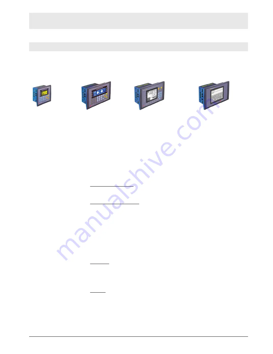
Vision OPLCs are programmable logic controllers that comprise an integral operating panel 

containing a graphic LCD screen and a keyboard.  All models offer the same PLC features. 

Operating panel features differ according to model. 

V230 

LCD + Keyboard 

V260 

LCD + Keyboard 

V280 

Touch Keyboard 

V290 

Touchscreen only 

Communications 

2 serial ports: RS232 (COM1), RS232/RS485 (COM2)

1 CANbus port

The user can order and install an additional port. Available port

types are: RS232/RS485, and Ethernet

Communication Function Blocks include: SMS, GPRS, MODBUS

serial/IP Protocol FB enables PLC to communicate with almost

any external device, via serial or Ethernet communications

I/O Options 

Vision supports digital, high-speed, analog, weight and temperature 

measurement I/Os via: 

Snap-in I/O Modules

Plug into the back of the controller to provide an on-board I/O 

configuration 

I/O Expansion Modules

Local or remote I/Os may be added via expansion port or CANbus

Information Mode 

This mode enables you to: 

View & Edit operand values, COM port settings, RTC and screen

contrast/brightness settings 

Calibrate the touchscreen

Stop, initialize, and reset the PLC

To enter Information Mode, press the <i> button for several seconds. 

Programming 

Software, 

& Utilities 

The Unitronics Setup CD contains VisiLogic freeware and other utilities 

VisiLogic

Easily configure hardware and write both HMI and Ladder control 

applications; the Function Block library simplifies complex tasks 

such as PID. Write your application, and then download it to the 

controller via the programming cable included in the kit 

Utilities

These include UniOPC server, Remote Access for remote  

programming and diagnostics, and DataXport for run-time data logging 

To learn how to use and program the controller, as well as use utilities such 

as Remote Access, refer to the VisiLogic Help system. 

Summary of Contents for Vision 230

Page 1: ...alog weight and temperature measurement I Os via Snap in I O Modules Plug into the back of the controller to provide an on board I O configuration I O Expansion Modules Local or remote I Os may be added via expansion port or CANbus Information Mode This mode enables you to View Edit operand values COM port settings RTC and screen contrast brightness settings Calibrate the touchscreen Stop initiali...

Page 2: ...duct the user must read and understand this document All examples and diagrams are intended to aid understanding and do not guarantee operation Unitronics accepts no responsibility for actual use of this product based on these examples Please dispose of this product according to local and national standards and regulations Only qualified service personnel should open this device or carry out repai...

Page 3: ...Installation Guide Unitronics 3 Mounting Dimensions V230 V260 280 290 ...

Page 4: ... The mounting panel cannot be more than 5 mm thick To minimize electromagnetic interference mount the controller on a metal panel and earth the power supply according to the details on page 5 1 Make a panel cut out that suits your model controller V230 Cut out Dimensions V260 280 290 Cut out Dimensions ...

Page 5: ...n the sides of the controller as shown in the figure to the right 5 Tighten the bracket screws against the panel Hold the bracket securely against the unit while tightening the screw 6 When properly mounted the controller is squarely situated in the panel cut out as shown below 5BWiring General This equipment is designed to operate only in SELV PELV Class 2 Limited Power environments All power sup...

Page 6: ...ows Use a metal cabinet Connect the functional earth terminal as described on page 5 Use only the grounding cable provided with the controller Connect the 0V terminal to the earth ground of the system at one point preferably as near to the controller as possible Power Supply The controller requires an external 12 or 24VDC power supply The permissible input voltage range is 10 2 28 8VDC with less t...

Page 7: ...nal 2 0V reference 2 RS232 signal 3 TXD signal 3 RS232 signal 4 RXD signal 4 RS232 signal 5 0V reference 5 RS232 signal 6 DSR signal 6 B signal Standard programming cables do not provide connection points for pins 1 and 6 When a port is adapted to RS485 Pin 1 DTR is used for signal A and Pin 6 DSR signal is used for signal B RS232 to RS485 Changing Jumper Settings The port is set to RS232 by facto...

Page 8: ...ler 2 Open the controller by inserting a flat bladed screwdriver into the slots located on the side of the controller then carefully prying off the rear panel 3 Locate the jumpers and then change the settings as required Settings are shown on page 7 4 Close the controller by snapping the plastic cover back in its place Re installing a Snap in I O Module 1 Line the circular guidelines on the contro...

Page 9: ...the controller Place terminators at each end of the CANbus network Resistance must be set to 1 121Ω 1 4W Connect ground signal to the earth at only one point near the power supply The network power supply need not be at the end of the network CANbus Connector Samara tel 7 846 273 95 85 samara klinkmann spb ru Yekaterinburg tel 7 343 287 19 19 yekaterinburg klinkmann spb ru St Petersburg tel 7 812 ...

Reviews: