


Adjustment
Classic P3 60-150 A
01/2018 - V1
18
Dis
play
s
5.3
Displays
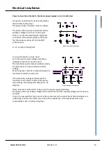
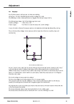
The thyristor power sections have an internal watchdog.
If there are no errors the BTB signal provides a voltage of >+10V.
The BTB relay on the control electronics is triggered via the test output X3:25.
The BTB signal voltage is <2V if the following errors occur:
Auxiliary voltage:
+24V, +15V, -15V
Power supply:
fuse failure, connection sequence, under-voltage
In case of errors or failure the power section is immediately internally disabled without delay.
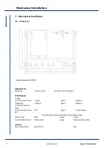
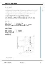
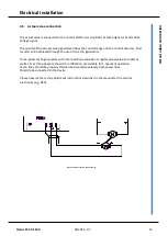
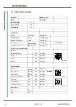
The current and the voltage can be measured in the load circuit (motor circuit) by means of
multimeters.
Manuals-Zeichnungen-P3-A054-Motor-Mess
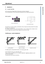
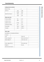
The dc current can be measured by means of measuring instruments which indicate mean values
or by instruments which indicate actual values. When measuring the dc current with these
different measuring instruments there will be measuring errors which are determined by the form
factor. For rated device current and the correct motor chokes the actual value is 1 to 5% higher
than the mean value.
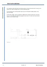
The motor voltage is measured as dc voltage.
The max. dc voltage must not be superior to 1.12 x power supply.
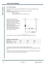
If the speed command value (X1:6 (REG)) or the current command value (X3:16 or X4:15) are
positive, the voltage across terminal 10 is negative against the terminal 13.
The signals of the current and the speed can be measured across the terminals X2:109 and X2:111
of the control electronics REG
The measured speed value across terminal X2:109 is -5V at +100% speed.
The measured current value across terminal X2:111 is +5V at +200% type current.


