


13 01/2018 - V1
Classic
P3 60-150 A
Electrical installation
M
ot
or
co
nnect
io
n
4.4
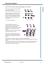
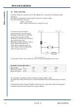
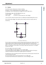
Motor connection
Armature chokes are necessary only for a few applications, e.g. quiet motor operation (stage
technique).
The motor is connected to the terminals 10 and 13 via an armature choke.
Min. armature choke inductance:
-L 4[mH] = UA/IA x 0.8
(Motor voltage divided by armature voltage. times 0.8)
:
The motor lines should only be
switched during a current-free state.
Switching off under current will create
arcing across the switch contacts.
Switching on while the drive is enabled
will cause the fuse to fail.
RNB resistors (brake resistors in case of
power supply failure) are to be
connected in parallel directly to the
motor armature without isolating the
motor from the control unit .
Zeichnungen-P3/P3-Motor-V647.1
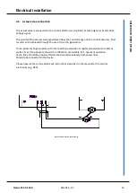
At the output of the armature choke the motor line is protected against short-circuits.
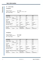
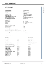
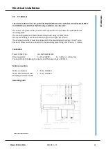
Conductor cross-section (min.)
Type current
A
60
120
150
Mains power supply mm²
6
16
25
Motor connection
mm²
10
25
35
The conductor cross-sections must be rated for continuous motor current.
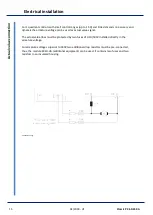
The power lines and motor lines are to be routed separately from sensitive measuring and control
lines.
Compared to transistor chopper amplifiers the thyristor servo drives have little electro-magnetic
and electro-static interferences which can easily be filtered.


