


UT Twin87
Twin-Circuit Condensor Microphone
9
Owner’s Manual
Version 1.0 as of 11/15/2021
Additional Support
Visit www.unitedstudiotech.com for additional
support.
UT Twin87
Twin-Circuit Condensor Microphone
8
Owner’s Manual
Version 1.0 as of 11/15/2021
Additional Support
Visit www.unitedstudiotech.com for additional
support.
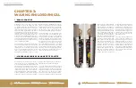
1.5
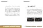
ENGAGING THE RF FILTER
To access filter dip switch, un
-
screw bottom bell counter-
clockwise from base of micro-
phone, then gently slide out
brass body tube.
The RF filter should be en
-
gaged when used in radio
broadcasting, or when radio
interference is an issue. The
UT Twin87 ships with the RF
filter disengaged by default.
To engage the filter, lower
switch positions 1 and 5, and
raise switch positions 2, 3,
and 4 (see Fig. 1). To bypass
the RF filter, raise switch po
-
sitions 1 and 5, while lowering
positions 2, 3, and 4 (see Fig.
2). Switch position 6 should
always be lowered.
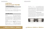
The RF filter present on lat
-
er incarnations of the 87-
type design is a source of
much controversy, with some
claiming it to be a useful
problem solver, while others
claim it detracts from the
sound. The UT Twin87’s filter
section has been ever slightly
‘sweetened’ by our choice of
higher grade components,
and selectable for use in both
Modern and Vintage modes.
While exceptionally subtle, a
trained ear will detect a slight
focus of the upper top end
when the filter is engaged,
with wide but definite ‘book
-
ends’ placed on the sound
field. With the filter disen
-
gaged, the top end may ap-
pear more natural, open, and
extended.
Chapter 1: Now Let’s Get Started!
1.5 Engaging the RF Filter
Chapter 1: Now Let’s Get Started!
1.4 Mitigating “Real World” Problems
Fig. 1: RF Filter Engaged
Fig. 2: RF Filter Bypassed
earth ground on the IEC pow-
er connector for that device.
Things become tricky if this
device itself does not have a
3-pin standard IEC power ca-
ble, but instead uses a 2 pin
‘wall-wart’ or ‘line-lump’ sup-
ply. In some cases, you may
have a small interface which
has no power supply, relying
on bus power from a com-
puter’s USB, firewire, or Thun
-
derbolt connector. This situ-
ation is sometimes referred
to as ‘vicarious grounding’,
where a ground connection
is passed through several
devices through various an-
alog and digital cables be-
fore finally connecting to the
‘house grounding’. Comput-
ers, unfortunately, can be
a source of significant EMI
(electro-magnetic interfer-
ence). While these situa-
tions cannot always be fully
remedied, especially with
field recording; at least being
aware of these potential is-
sues when setting up and se-
lecting equipment can spare
you from the worst of these
effects.
For instance, if your inter-
face, laptop, preamp, etc. all
have no earth ground, which
is entirely possible with lap-
top recording; you may in-
tentionally select a device
to connect in the chain that
the microphone can ground
to. An example of this would
be connecting an outboard
preamp or other processor to
the interface, so long as it has
a 3 pin IEC power cable that is
plugged in and an audio con-
nection such as XLR or TRS
that can connect to the in-
terface. This will ‘ground’ the
interface, even if the piece of
outboard gear is not being
used in the signal chain. Ad-
ditionally, well constructed
and shielded digital cables,
particularly with robust fer-
rite rings clamped on one or
both ends, can help reduce
any noise contamination
from a digital device into the
microphone.
In any case, for safety and
good operation, it cannot
be recommended that the
UT Twin87 be operated in a
situation where there is no
access to earth ground to
ground the microphone’s pin
1 connector.