


UT Twin87
Twin-Circuit Condensor Microphone
5
Owner’s Manual
Version 1.0 as of 11/15/2021
Additional Support
Visit www.unitedstudiotech.com for additional
support.
UT Twin87
Twin-Circuit Condensor Microphone
4
Owner’s Manual
Version 1.0 as of 11/15/2021
Additional Support
Visit www.unitedstudiotech.com for additional
support.
Chapter 1: Now Let’s Get Started!
1.2 Hardware Controls
Chapter 1: Now Let’s Get Started!
1.1 Connections and Power
CHAPTER 1:
NOW LET’S GET STARTED!
1.1
CONNECTIONS AND POWER
1.2
HARDWARE CONTROLS
Pattern select
- omnidirectional, cardioid, and
figure of eight.
In cardioid mode, the UT Twin87 takes the mi-
crophone out of the pattern select circuitry all
together and decouples the rear diaphragm, a
mod or setting sometimes referred to as ‘true
cardioid’. This has some performance advan-
tages over normal ‘switched’, or active cardioid
which still goes through the pattern select cir-
cuitry. Signal level and signal to noise ratio are
slightly enhanced.
Modern/Vintage
- This setting allows the
user to choose between the earliest 87-style
microphone circuit and the more modern re-
productions.
HPF
- gradual slope rumble filter tuned for voice
broadcast, 12 dB down at 80hZ
-10dB pad
- attenuates amplifier section by 10dB
to provide greater headroom for loud sources.
The UT Twin87 is a multi-pattern, large dia-
phragm, transformer-balanced condenser mi-
crophone designed for a very wide range of re-
cording studio applications. Its operation is fairly
straightforward. As with any microphone; the
more attention given to setup and placement,
the better the results will be. The UT Twin87 fea-
tures a high pass filter for eliminating subsonic
information such as floor vibration and rumble,
and a -10 pad for use in very loud sound pressure
situations such as kick drum, guitar amplifiers,
and especially loud vocalists.
HOW TO KNOW IF YOU NEED THE PAD
ENGAGED?
It is good practice, unless you are certain you
will need it, to start without the pad engaged.
You will know you need the pad if the signal
is distorted, clipping, or ‘flatlined’ even after
properly spacing the microphone from its
source. The pad will allow for an additional
The UT Twin87 requires 2 things in order to
properly function: a 3 pin XLR cable, and 48V
phantom power.
The first is simple; plug the XLR cable to the
output jack on the bottom of the UT FET47.
Then connect the cable to your recording de-
vice, preamp, or mixing console. Ensure that
the cable is properly working...
Sorry, we had to spell that out.
Engage 48V phantom power on your device.
If your device does not provide 48V phantom
power, an external, dedicated power supply
will be required for operation.
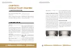
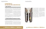
Fig. 1: Front of the UT Twin87. Left side controls are for Pattern
Select. Right side controls are for Modern/Vintage.
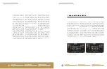
Fig. 2: Rear of the UT Twin87. Left side controls are HPF. Right
side controls are Pad.
10dB of headroom in the amplifier circuit for
these situations.
WHEN TO ENGAGE THE HIGH PASS FILTER?
In studio recording, we feel it is usually good
practice to record an audio source at ‘full
bandwidth’ and to precisely tailor any ban-
dlimiting in the modern workstation. This
provides much more accuracy than a single
switch on a microphone can provide; and the
switch at this point is more a carryover from
an earlier time. There are a number of sound
sources, however, where one can be fairly
sure that frequencies below the switch cutoff
frequency are not going to play a major part
in the makeup of the audio source, or at least
not in the finished (edited/processed) form
that the audio track will take. This includes
voice, guitar, drum overhead, and possibly
some acoustic instruments. This is particu-
larly true of live voice broadcast (podcast, ra-
dio broadcast) and narration (books on tape,
etc). Because low frequencies have very large
waveforms, a high pass filter on the micro
-
phone can sometimes reduce the chances of
clipping or allow a slightly hotter signal to be
captured, without the damage from moving
microphone stands, doors, and rumble from
nearby traffic, etc. As a general rule, if engag
-
ing the HPF causes no audible loss to the
‘body’ of the source signal; it is safe to engage.
If it does feel that it takes something away,
and if the application is professional record-
ing, then best to not engage the switch and
tailor the signal at a later point in the process.
WHEN TO USE A POP FILTER?
It is generally good advice to use a pop filter
any time you are recording a vocalist. You
should always get the best pop filter you can,
one that is as sonically neutral as possible.
Once you have found the proper distance for
spacing a vocalist from the microphone; the
pop filter can be set in place to properly main
-
tain that spacing.