1-6-4
T6627EA
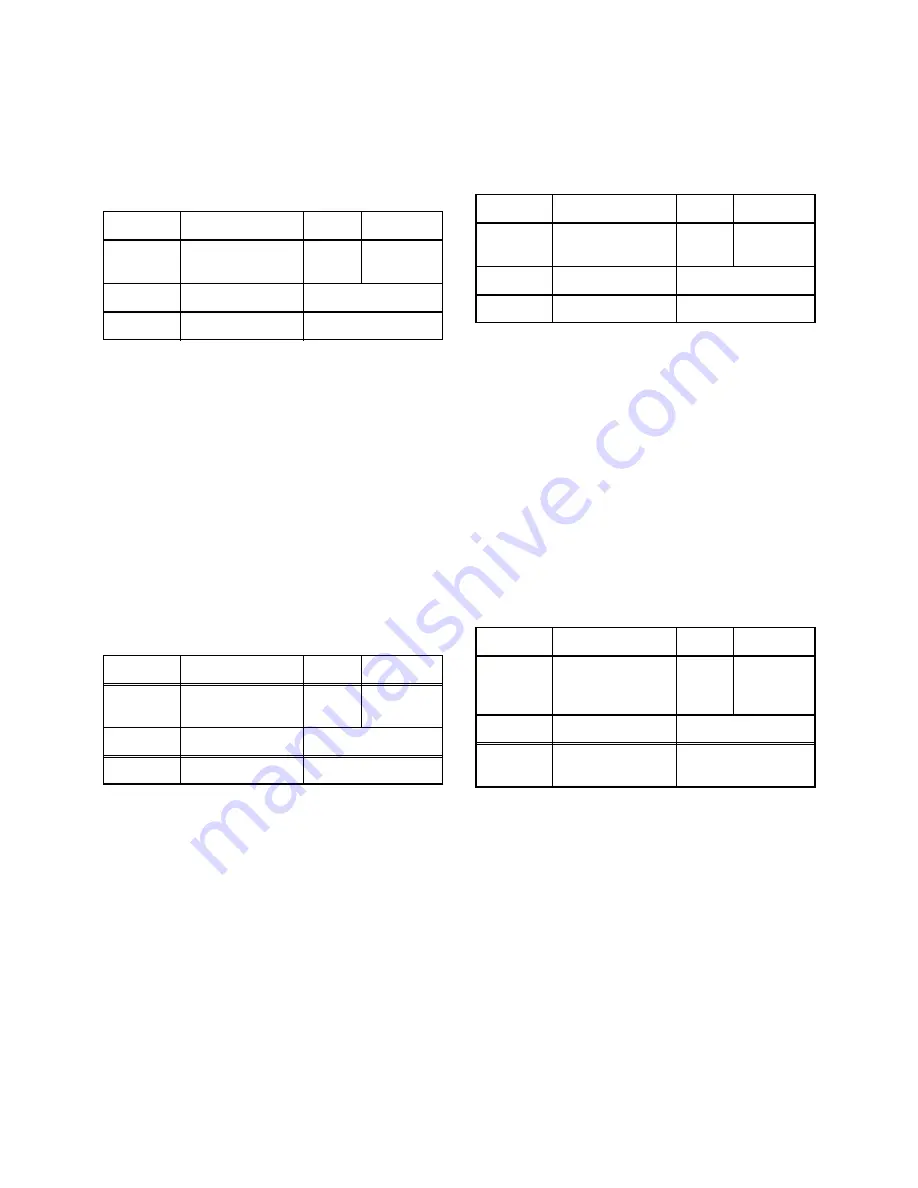
5. V. Size Adjustment
Purpose: To obtain correct vertical height of screen
image.
Symptom of Misadjustment: If V. Size is incorrect,
vertical height of image on the screen may not be
properly displayed.
1. Enter the Service mode. (See page 1-6-1.)
Press [9] button on the remote control unit and
select V-S mode. (Press [9] button then display will
change to V-P and V-S).
2. Input monoscope pattern and leave it for at least 20
minutes.
3. Press [PROG+/PROG-] buttons on the remote con-
trol unit so that the monoscope pattern is 90
±
5% of
display size and the circle is round.
6. V. Shift Adjustment
Purpose: To obtain correct vertical position of screen
image.
Symptom of Misadjustment: If V. position is incor-
rect, vertical position of image on the screen may not
be properly displayed.
1. Enter the Service mode. (See page 1-6-1.)
Press [9] button on the remote control unit and
select V-P mode. (Press [9] button then display will
change to V-P and V-S).
2. Input monoscope pattern and leave it for at least 20
minutes.
3. Press [PROG+/PROG-] buttons on the remote con-
trol unit so that the top and bottom of the mono-
scope pattern are equal to each other.
7. H. Shift Adjustment
Purpose: To obtain correct horizontal position and
size of screen image.
Symptom of Misadjustment: Horizontal position and
size of screen image may not be properly displayed.
1. Enter the Service mode. (See page 1-6-1.)
Press [8] button on the remote control unit and
select H-P mode.
2. Input monoscope pattern and leave it for at least 20
minutes.
3. Press [PROG+/PROG-] buttons on the remote con-
trol unit so that the left and right side of the mono-
scope pattern are equal to each other.
4. Turn the power off and on again.
8. Cut-off Adjustment
Purpose: To adjust the beam current of R, G, B, and
screen voltage.
Symptom of Misadjustment: White color may be
reddish, greenish or bluish.
Notes:
Screen Control (FBT) --- H.V./Power Supply CBA
FBT= Fly Back Transformer
Use the Remote Control Unit
1. Degauss the CRT and allow CRT to operate for 20
minutes before starting the alignment.
2. Set the screen control to minimum position. Input
the Black raster signal from RF (or Ext.) input.
3. Enter the service mode. (See page 1-6-1.)
Dimmed horizontal line appears on the CRT.
4. To enter the C/D/S mode, press the [VOL-] button
on the remote control unit.
5. To enter the CUT OFF (R) mode, press [1] button
on the remote control unit.
6. Turn the screen control up until dimmed horizontal
line appears.
Test point
Adj. Point
Mode
Input
Screen
PROG+/PROG-
buttons
RF
(or Ext.)
Monoscope
Tape
M. EQ.
Spec.
---
Pattern Generator
90
±
5%
Test point
Adj. Point
Mode
Input
Screen
PROG+/PROG-
buttons
RF
(or Ext.)
Monoscope
Tape
M. EQ.
Spec.
---
Pattern Generator
90
±
5%
Test point
Adj. Point
Mode
Input
Screen
PROG+/PROG-
buttons
RF
(or Ext.)
Monoscope
Tape
M. EQ.
Spec.
---
Pattern Generator
90
±
5%
Test point
Adj. Point
Mode
Input
Screen
Screen-Control,
PROG+/PROG-
buttons
RF
(or Ext.)
Black Ras-
ter
Tape
M. EQ.
Spec.
---
Pattern Generator
See Reference
Notes below
Summary of Contents for TVC5044
Page 17: ...1 5 4 T6627DC Fig 4 S 11 S 11 S 11 S 11 Anode Cap 11 CRT CRT CBA...
Page 36: ...Main 1 5 Schematic Diagram 1 8 3 1 8 4 T6627SCM1...
Page 37: ...Main 2 5 Schematic Diagram 1 8 5 1 8 6 T6627SCM2...
Page 38: ...Main 3 5 Schematic Diagram 1 8 7 1 8 8 T6627SCM3...
Page 39: ...Main 4 5 Schematic Diagram 1 8 9 1 8 10 T6627SCM4...
Page 40: ...1 8 11 1 8 12 T6627SCM5 Main 5 5 Schematic Diagram...
Page 42: ...1 8 15 1 8 16 H V Power Supply 2 2 Schematic Diagram T6627SCP2...
Page 43: ...1 8 17 1 8 18 T6627SCCRT CRT Schematic Diagram...
Page 44: ...1 8 19 1 8 20 T6627SCT Text Schematic Diagram...
Page 53: ...1 14 3 T6627PEX Packing S3 S6 X3 S2 X4 X1 TAPE S1 FRONT S4 X2 3 X2 7 X2 14 X2 15...
Page 86: ...2 4 9 Z13PDA Fig DM16 43 41 42 L 13 Fig DM17 44 45 Slide P 9...


