background image

-9-

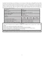
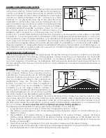
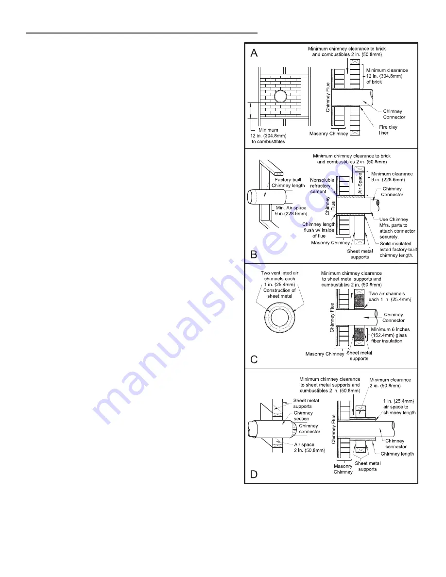
METHOD A -

 12” (304.8 mm) Clearance to Combustible Wall 

Member:  Using  a  minimum  thickness  3.5”  (89  mm)  brick 

and  a  5/8”  (15.9  mm)  minimum  wall  thickness  clay  liner, 

construct a wall pass-through. The clay liner must conform 

to ASTM C315 (Standard Specification for Clay Fire Linings) 

or its equivalent. Keep a minimum of 12” (304.8 mm) of brick 

masonry between the clay liner and wall combustibles. The 

clay liner shall run from the brick masonry outer surface to 

the inner surface of the chimney flue liner but not past the 

inner surface. Firmly grout or cement the clay liner in place 

to the chimney flue liner.

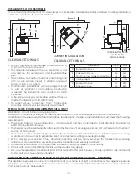
METHOD B - 

9” (228.6 mm) Clearance to Combustible Wall 

Member:  Using  a  6”  (152.4  mm)  inside  diameter,  listed, 

factory-built Solid-Pak chimney section with insulation 

of  1”  (25.4  mm)  or  more,  build  a  wall  pass-through  with  a 

minimum 9” (228.6 mm) air space between the outer wall of 

the chimney length and wall combustibles. Use sheet metal 

supports  fastened  securely  to  wall  surfaces  on  all  sides, 

to maintain the 9” (228.6 mm) air space. When fastening 

supports to chimney length, do not penetrate the chimney 

liner (the inside wall of the Solid-Pak chimney). The inner end 

of the Solid-Pak chimney section shall be flush with the inside 

of the masonry chimney flue, and sealed with a non-water 

soluble refractory cement. Use this cement to also seal to 

the brick masonry penetration.

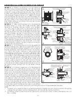
METHOD C - 

6” (152.4 mm) Clearance to Combustible Wall 

Member: Starting with a minimum 24 gage (.024” [.61 mm]) 

6” (152.4 mm) metal chimney connector, and a minimum 

24 gage ventilated wall thimble which has two air channels 

of  1”  (25.4  mm)  each,  construct  a  wall  pass-through. 

There  shall  be  a  minimum  6”  (152.4  mm)  separation  area 

containing fiberglass insulation, from the outer surface of the 

wall thimble to wall combustibles. Support the wall thimble, 

and cover its opening with a 24-gage minimum sheet metal 

support.  Maintain  the  6”  (152.4  mm)  space.  There  should 

also be a support sized to fit and hold the metal chimney 

connector. See that the supports are fastened securely to 

wall surfaces on all sides. Make sure fasteners used to secure 

the metal chimney connector do not penetrate chimney 

flue liner.

METHOD D - 

2” (50.8 mm) Clearance to Combustible Wall 

Member: Start with a solid-pak listed factory built chimney 

section at least 12” (304 mm) long, with insulation of 1” (25.4 

mm) or more, and an inside diameter of 8” (2 inches [51 mm] 

larger than the 6” [152.4 mm] chimney connector). Use this 

as a pass-through for a minimum 24-gauge single wall steel 

chimney connector. Keep solid-pak section concentric with 

and  spaced  1”  (25.4  mm)  off  the  chimney  connector  by 

way of sheet metal support plates at both ends of chimney 

section. Cover opening with and support chimney section 

on both sides with 24 gage minimum sheet metal supports. 

See that the supports are fastened securely to wall surfaces 

on all sides. Make sure fasteners used to secure chimney flue line do not penetrate the inner liner.

NOTES:

1. 

Connectors to a masonry chimney, excepting method B, shall extend in one continuous section through the 

wall pass-through system and the chimney wall, to but not past the inner flue liner face.

2. 

A chimney connector shall not pass through an attic or roof space, closet or similar concealed space, or a 

floor, or ceiling.

COMBUSTIBLE WALL CHIMNEY CONNECTOR PASS-THROUGHS

Summary of Contents for VOGELZANG TR007E

Page 1: ...ne lesquels sont reconnus dans l tat de la Californie comme causant le cancer et des malformations cong nitales ou autres dommages au f tus Pour obtenir plus de renseignements veuillez consulter le si...

Page 2: ...with your records for any claims Combustible Wood Colors Metallic Black Flue Pipe Diameter 6 153 mm Flue Pipe Type Standard Single Wall or Double Wall Black or Blued Steel 2100 F 650 C Minimum Chimney...

Page 3: ...Attach two corner pieces A to the center section B of skirting and secure with four 4 truss head screws 2 Attach the side skirting sections C D to the corner pieces and secure with four 4 truss head s...

Page 4: ...IN THIS HEATER KEEP ALL SUCH LIQUIDS WELL AWAY FROM THE HEATER WHILE IT IS IN USE IN THE EVENT OF A CHIMNEY FIRE PUSH THE AIR CONTROL FULL CLOSED TO DEPRIVE THE FIRE OF OXYGEN CALL THE FIRE DEPARTMENT...

Page 5: ...le home with 8 GA copper wire using a serrated or star washer to penetrate paint or protective coating to ensure grounding When moving your mobile home all exterior venting must be removed while the m...

Page 6: ...heating and cooling contractor or certified wood stove installer Drill a 5 hole through the wall at the desired point of entry The point of entry should be at or below the level of the intake air tube...

Page 7: ...o the room through appliance and chimney connector joints An uncontrollable burn or excessive temperature indicates an excessive draft CHIMNEY Your wood stove may be hooked up with a 6 factory built o...

Page 8: ...as recommended by the manufacturer The chimney must be the required height above the roof or other obstructions for safety and proper draft operation MASONRY CHIMNEY Ensure that a masonry chimney meet...

Page 9: ...h has two air channels of 1 25 4 mm each construct a wall pass through There shall be a minimum 6 152 4 mm separation area containing fiberglass insulation from the outer surface of the wall thimble t...

Page 10: ...ns Under extreme conditions it may rot instead of drying This point cannot be over stressed the vast majority of the problems related to the operation of a wood stove is caused by the fact that the wo...

Page 11: ...heater is designed to burn natural wood only Higher efficiencies and lower emissions generally result when burning air dried seasoned hardwoods as compared to softwoods or to green or freshly cut har...

Page 12: ...the best heating burn rates after a good fire is established a lower burn rate may be a better option for efficient heating A lower burn rate slows the flow of usable heat out of the home through the...

Page 13: ...minute point of loading your fuel the primary air slide should be set at the medium setting which is about 1 2 inch open from the fully closed position For a low burn setting once the high burn or med...

Page 14: ...ed and air blown clean Make sure the blades do not have build up CAUTION Do not overfire appliance You are overfiring if any part of the appliance glows red Close the door and shut damper immediately...

Page 15: ...ly Do not abuse the glass door by striking or slamming shut Do not use the stove if the glass is broken If the glass on your stove breaks replace only with the glass supplied from your heater dealer N...

Page 16: ...E MENT WIRING MUST HAVE EQUIVALENT INSULA TION AND TEMPERATURE RATING 105 C CAUTION MOVING PARTS CAN CAUSE INJURY DO NOT OPERATEWITH COVER REMOVED DANGER SHOCKHAZARD DISCONNECT POWERSOURCEBEFOREINSTAL...

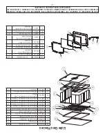
Page 17: ...2279 Hearth Trim 1 7 69912 Ash Drawer 1 8 26548 Ash Drawer Support 1 9 26541 Left Side Skirt 1 10 40597 Skirt Corner 2 11 26546 Front Skirt 1 12 26553 Right Side Skirt 1 13 69911 Pedestal 1 IN ORDER T...

Page 18: ...9 20 5 892281 1 5 Firebrick 2 6 40595 Half Brick Ash Plug 1 7 86698 Tube 1 Secondary Air Tube 4mm 1 8 86699 Tube 2 3 Secondary Air Tube 3mm 2 9 86700 Tube 4 Secondary Air Tube 2 5mm 1 10 86701 Tube 5...

Page 19: ...19 Notes...
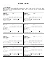
Page 20: ...07 Date _____________________ Engineer Name ________________________________ License No ____________________________________ Company _____________________________________ Telephone No _______________...

Page 21: ...orsque vous nous crivez donnez toujours le num ro de mod le complet qui se trouve sur la plaque signal tique fix e sur l appareil de chauffage Lors de commandes de pi ces d tach es donnez toujours les...

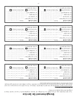
Page 22: ...____________________________ Service de 07 Date _____________________ Nom de l ing nieur ____________________________ N de licence _________________________________ Compagnie _________________________...

Page 23: ...brique r fractaire 2 6 40595 Bouchon de cendre demi brique 1 7 86698 tube d air secondaire 1 4mm 1 8 86699 tube d air secondaire 2 3 3mm 2 9 86700 tube d air secondaire 4 2 5mm 1 10 86701 tube d air...

Page 24: ...p rieure 1 6 892279 Garniture de foyer 1 7 69912 Tiroir cendres 1 8 26548 Support de tiroir cendres 1 9 26541 Jupe c t gauche 1 10 40597 Coin de jupe 2 11 26546 Jupe avant 1 12 26553 Jupe c t droit 1...

Page 25: ...ctrique entrer en contact avec une surface chaude Garder le fil lectrique 12po 30cm au moins de la surface du po le ou des conduits ATTENTION PI ces mobiles pouvant causer des blessures Ne pas faire f...

Page 26: ...ait rayer Utilisez un produit sp cialis disponible dans les magasins o les po les bois sont vendus Le verre ne doit tre lav qu froid ATTENTION LES CENDRES POURRAIENT CONTENIR DES EMBRES CHAUDES M ME A...

Page 27: ...ustion lente Par cons quent des r sidus de cr osote s accumulent sur le rev tement du conduit de fum e Lorsqu elle est allum e cette cr osote fait un feu extr mement lev Le raccord de chemin e et la c...

Page 28: ...E Pour un fonctionnement optimal de cet appareil il est recommand de le faire fonctionner avec une charge de bois approximativement quivalente la hauteur des briques r fractaires Il est important de n...

Page 29: ...20 minutes A rez de fa on suffi sante pour liminer la fum e ou les odeurs caus es par ces feux ATTENTION ne laissez pas l appareil sans surveillance avec la porte ouverte Remarque utilisez uniquement...

Page 30: ...e sciure impr gn e de cire ou de b ches avec des additifs chimiques Les b ches fabriqu es partir de sciure de bois compress e 100 peuvent tre br l es mais faites attention br ler trop de ces b ches en...

Page 31: ...m me pourrir au lieu de s cher On ne saurait trop soulign que la vaste majorit des probl mes li s au fonctionnement d un insert bois est caus e par le fait que le bois utilis tait trop humide ou avai...

Page 32: ...bustible Commencez avec une partie de chemin e Solid Pak fabriqu e en usine agr e d au moins 12 po 304 mm de diam tre int rieur avec une isolation de 1 po 25 4 mm ou plus et un raccord de chemin e de...

Page 33: ...gagement de 2 po Chapeau homologu Mur combustible Consulter D gagement des combustibles Protecteur de plancher Conduit de raccordement de chemin e Solive de toit combustible Chemin e homologu Mitre So...

Page 34: ...mp rature excessive indique un tirage excessif Pente de po par pied Partie m le vers le bas 3 vis Vers l appareil Installer l extr mit sertie vers le po le Direction de la circulation des gaz de condu...

Page 35: ...nt agr ou d un installateur de po le bois certifi Percez un trou de 5 pouces travers le mur au point d entr e souhait Le point d entr e doit tre au niveau ou en dessous du niveau du tuyau d air d admi...

Page 36: ...lations de maisons mobiles doivent r pondre aux exigences suivantes Le chauffe eau doit tre connect une chemin e pr fabriqu e conforme la norme CAN ULC S629 norme pour les chemin es pr fabriqu es 650...

Page 37: ...icile Le po le doit par cons quent tre install dans la pi ce o vous passez le plus de temps et dans la pi ce la plus spacieuse possible Rappelez vous que les po les bois produisent une chaleur rayonna...

Page 38: ...base du socle Fixez deux pi ces d angle A la section centrale B de la plinthe et fixez les avec quatre 4 vis t te bomb e 2 Fixez les plinthes lat rales C et D aux pi ces d angle et fixez les avec qua...

Page 39: ...cier noir ou bronz 2100 F 650 C Hauteur minimale de la chemin e 12 pi 3 7 m Longueur maximale des b ches 18 po 458 mm lectrique 120VAC 0 55A 60Hz Dimensions Profondeur Largeur Hauteur G n rales Profon...

Page 40: ...nnus dans l tat de la Californie comme causant le cancer et des malformations cong nitales ou autres dommages au f tus Pour obtenir plus de renseignements veuillez consulter le site www P65warnings ca...

Reviews: