United States Stove American Harvest 6039I Owner'S Manual Download Page 22

22

USSC

CIRCUIT BOARD FUNCTIONS

Draft Fan

Agitator

Auger

Room Fan

Automatic Shutdown

Normal Operation

COMPONENT

OPERATION START

OPERATION END

START-UP SEQUENCE OF EVENTS

Once the control panel is turned to on, a timer begins that will start, stop and continue operation of the 

American

Harvest

 as a preset temperature is achieved.

Starts Immediately

Three minutes after starting the agitator will
begin to turn

Three minutes after starting the auger will
begin to turn

Begins when 110 degrees is reached.

If after 15 minutes, the heater


has not reached

the preset operating temperature, the unit will
begin to automatically shut down.

If after 15 minutes the preset operating tem-
perature of 110 degrees is achieved, normal
operation will continue.

Will continue until shutdown. Shutdown will
occur when the operating temperature is
below 90 degrees.

Will continue intermediately, as determined by
the “HEAT SETTING”, until shutdown

The auger will continue at the feed rate
specified by the “HEAT SETTING”.

NOTE: 

Safety switches, HI limit and vacuum

sensor, must be activated to continue proper
operation.

Will continue to operate until the heater


cools

down to below 90 degrees. This may take
several minutes up to an hour.

Should the timer expire before the preset
operating temperature is achieved, simply
reset the stove by pressing the “ON” buttton.

Operation will continue until either the
heater’s


control is to the “OFF” position, or

the operating temperature falls below 90
degrees. At such time the heater will default
to the “Automatic Shut Down”.

Draft Fan

Agitator

Auger

Room Fan

Automatic Shutdown

COMPONENT

SHUTDOWN

OPERATION END

Unchanged operation until preset “OFF” tem-
perature is achieved.

Continues at a lower sequence

Slows down to a “

HALF SETTING” 

for 10

minutes and then to a 

“QUARTER SETTING”

for the duration of the shutdown.

Unchanged operation until preset “OFF” tem-
perature is achieved.

If the heater’s


“HI LIMIT” sensor snaps open,

this will cause an automatic shutdown. An
error code will be displayed (Err1)

.

 NOTE: 

“HI

LIMIT” errors are usually the result of operat-
ing at the highest heat setting for long peri-
ods of time, room fan failure or loose wire
connection.

Continues until the operating temperature falls
below 90 degrees. May take several minutes
up to an hour.

Continues until the operating temperature falls
below 90 degrees.

The auger will continue at the lower feed
rates until the operating temperature falls
below 90 degrees.

NOTE: 

Safety switches, HI limit and vacuum

sensor, must be activated to continue
proper operation.

Will continue to operate until the heater


cools

down to below 90 degrees. This may take
several minutes up to an hour.

It is rare that the HI LIMIT temperature is
reached. However, should this error occur,
let the heater cool down for an hour then

restart.

SHUTDOWN SEQUENCE OF EVENTS

Once the 

Heater 

has reached the normal operating temperature and switched to the “OFF” position, the unit will

continue to operate on a much lower setting for 10 minutes. (Approximately half of the “1” setting). After 10 minutes the
auger will slow down further and continue at this feed rate until the heater’s


“LOW LIMIT SAFTEY” sensor tells the

control board it is safe to shutdown.

Summary of Contents for American Harvest 6039I

Page 1: ...ire officials about restrictions and installation requirements peculiar to your area Do Not Plug this appliance into an electrical outlet before reading and understanding all operations and always unp...

Page 2: ...st You ve purchased one of America s Finest Multifuel Burning Stoves By heating with fuels such as corn and pellets you re helping CONSERVE AMERICA S ENERGY CONGRATULATIONS BTU output will vary depend...

Page 3: ...crews have been tightened properly carefully set the heater back up on the legs 1 The Auger is packed in the hopper or ash pan and must be installed properly as illustrated below 2 Insert the Auger in...

Page 4: ...CB cable Route the board and cable through the opening and mount it to the Left Facade using two of the 10 x 1 2 phillips head screws provided Then attach the PCB cover to the back of the facade cover...

Page 5: ...USSC 5 COMPONENT LOCATION...

Page 6: ...c maintenance for proper operation and long life of the stove Read and follow the maintenance schedule closely DISCONNECT THE POWER CORD BEFORE SERVICING THIS STOVE A power surge protector is required...

Page 7: ...small to midsize kernel corn If the kernel size of the corn varies greatly or if you switch sources frequently you will get a less consistent burn Therefore purchasing corn from the same source will...

Page 8: ...all to Top Edge of Unit 8 in 203mm B Sidewall to Flue 13 in 330mm C Backwall to Flue 3 in 75mm D Backwall to Unit 9 in 228mm CORNER E Adjacent Wall to Flue 3 in 75mm F Adjacent Wall to Unit 4 in 100mm...

Page 9: ...USSC 9 CLEARANCES TO COMBUSTIBLES 6039I...

Page 10: ...and elbows should not be connected to the rear of the unit unless a 3 inch adapter is used Total length of horizontal vent must not exceed 48 4ft 1 200mm The maximum recommended vertical venting heig...

Page 11: ...in a burn back during high winds blowing directly up the air inlet during a simulta neous power failure see diagram above Blockage excessive length or extra bends in the air intake pipe will starve t...

Page 12: ...ARD INSTALLATION INSTRUCTION THE FOLLOWING REQUIREMENTS ARE MANDATORY FOR INSTALLATION IN A MOBILE HOME WARNING DO NOT INSTALL IN SLEEPING ROOM 1 Stove must be permanently bolted to the floor Remove t...

Page 13: ...90 Elbow 3 PL Vent Termination Cap Note Always check dimensions on unit before cutting hole in wall 3 Minimum Vertical Pipe Dimensional tolerance 1 4 12 1 8 11 3 4 10 1 16 EXHAUST OULET 3 DIA COMBUST...

Page 14: ...ATION CAP The Hearth Pad is not required under the unit if the floor is noncombustible but is required 6 inches 152mm beyond the front of the unit and 6 inches 152mm beyond each side of the door if th...

Page 15: ...ding on your installtion you might consider routing your cleanout tee as illustrated below for ease of cleaning The access panel in the right side facade allows you to reach the tee from the front sid...

Page 16: ...pas sage to chimney cavity Outside combustion air may be drawn through the chimney top or through an existing ash cleanout INSTALLATIONINTOAFACTORY BUILT METAL FIREPLACE When installing into a zero c...

Page 17: ...er tightening can cause the glass to break WARNING Do not operate unit with broken glass Do not substitute original factory glass You must use only factory authorized glass Do not slam door shut Do no...

Page 18: ...r to leave the stove in the automatic mode and adjust the manual draft slide to control the combustion air The room fan will come on once the unit has reached operating temperature 110 F By pressing t...

Page 19: ...led out more for higher heat settings Try opening a 1 4 inch at a time As you begin to have better understanding of how the heater operates and the amount of heat you require you can adjust the heat s...

Page 20: ...eaned out it could cause the agitator to jam USSC highly recommends an additive see Fuel Additive be added to your corn to eliminate these clinkers Contact your local dealer for availability and cost...

Page 21: ...he lower corners of the firebox Tap the sides of the burn chamber with a wooden stick Do not tap the firewall behind the burn box as it may damage the ceramic firebrick Scrape the fly ash from the cle...

Page 22: ...er will default to the Automatic Shut Down Draft Fan Agitator Auger Room Fan Automatic Shutdown COMPONENT SHUTDOWN OPERATION END Unchanged operation until preset OFF tem perature is achieved Continues...

Page 23: ...motor jammed or bad Draft Fan motor jammed or bad Room fan motor jammed or bad Display Indicators Several situations or events are indicated in normal operation by blinking display indicators or segme...

Page 24: ...ed rate is too HI for fuel reduce heat setting Inadequate combustion air available add outside combustion air Optional kit 69FAK 9 9 9 CAUSE Firepot burns out of fuel Hopper empty refill Door is open...

Page 25: ...USSC 25 WIRING DIAGRAM...

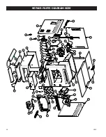
Page 26: ...26 USSC REPAIR PARTS DIAGRAM 6039...

Page 27: ...88106 Gasket Room Fan 1 31 80472 Fan Room 1 32 80507 Circuit Board 1 33 80488 Motor Drive 1 34 88111 Gasket Agitator Bracket 1 35 83534 Ring Retaining 1 36 25422 Bracket Agitator Bushing 1 37 891132 B...

Page 28: ...28 USSC 22 23 20 21 24 25 26 27 18 17 7 6 3 4 6 5 11 10 2 9 8 10 15 14 16 12 13 19 23 1 28 29 REPAIR PARTS 6039I...

Page 29: ...astic 1 16 25581MB Right Side Cabinet 1 17 25579MB Left Side Front Cabinet 1 18 25580MB Left Side Rear Cabinet 1 19 25578MB Back Cabinet 1 20 25587MB Weldment Facade Panel Right Side 1 21 89943 Knob C...

Page 30: ...g Parts Bag 1 Key Part No Descritption Qty 1 25491 Feed Door 1 2 25492 Handle Door 1 3 83506 Roll Pin 3 8 x 1 1 4 1 4 88112 Gasket 1 2 Sq Rope 5 ft 5 88087 Gasket Glass 1 x 3 16 4 ft 6 891131 Glass Ce...

Page 31: ...USSC 31 Notes...

Page 32: ...VE THE FULL MODEL NUMBER WHICH IS ON THE NAMEPLATE ATTACHED TO THE HEATER WHEN ORDERING REPAIR PARTS ALWAYS GIVE THE FOLLOWING INFORMATION AS SHOWN IN THIS LIST 1 THE PART NUMBER 2 THE PART DESCRIPTIO...

Reviews: