


USSC
19
LIGHTING INSTRUCTIONS
CAUTION: DO NOT USE CHEMICALS OR FLUIDS TO START THE FIRE
HOT WHILE IN OPERATION. KEEP CHILDREN, CLOTHING AND FURNITURE AWAY. CONTACT MAY CAUSE SKIN
BURNS.
Before lighting your heater for the first time, make sure that all items are out of the hopper, ash pan and
firebox area.
Press the “On” button and allow your heater to run for at least 4 minutes, to check for proper operation.
Once your heater is started, you will notice the draft fan starts immediately. If you press the “Heat Setting” button up, the
draft fan changes speed, increasing speed the higher the heat setting. After 3 minutes, the auger and agitator will start
rotating.
Note: The room fan will not operate at this time, as a temperature of at least 110 degrees must be reached
before operating. If proper operation of your heater is confirmed, you can add fuel to the hopper and allow the auger to
purge the fuel to the firepot.
TO START:
Turn the Heater to the “OFF” position and place a small handful of wood pellets or fire starting pellets (Pellets that already
contain fire starter) in the firepot.
Squirt only a small amount of fire starter gel on top of the wood pellets (NOT necessary if using fire starting pellets).
Light the fire starter and wait approx. 1-minute for it to start actively burning.
Press the “On” button, adjust the heat setting to read “Hr-2” and pull the damper out approximately 1 inches for this
heat setting. This will automatically match your feed rate with the proper combustion air. As you increase the heat
setting, your feed rate and combustion air increase together.
NOTE: Even if you are burning corn or other fuels in your unit, wood pellets make an excellent source of
starter fuel. Corn takes too much starter to properly ignite and get up to temperature.
Three minutes after turning the stove “On”, the auger will begin feeding fuel into the firepot along with the agitator
turning. You should have the starting fuel completely burning in the firepot as the agitator rotates. NOTE: If the starting
fuel is not burning hot enough, you may see the fire begin to go out as new fuel is being added. If this occurs, pressing
the “Auger Delay” button will allow the auger to pause for 1 minute. Pressing the “ON” button will resume the auger if
1 min. is too long. If not enough fuel is the reason for not burning, pressing and holding the “ON” button will allow the
auger to run continuously until you release the button.
Once the fuel starts burning aggresively, you can adjust the heat setting to your desired range. Make sure that you pull
the damper out approximately 1 inch. It may need to be pulled out more for higher heat settings. Try opening a 1/4 inch
at a time.
As you begin to have better understanding of how the heater operates and the amount of heat you require, you can adjust
the heat settings up or down to your satisfaction.
Never use gasoline, gasoline-type lantern fuel, kerosene, charcoal lighter fluid, or similar liquids to start or
“freshen up” a fire in this heater. Keep all such liquids well away from the heater while it is in use.
Overfire Protection - If the heater is being overfired, burned too hot, the heater will automatically shutdown to avoid
damage to components in the heater. Refer to “Lighting Instructions” for proper use.
•
•
•
•
•
•
•
•
•
Turning the stove off
Pressing the OFF button will cause the stove to enter a shutdown mode. If the stove has reached operating temperature, the
OFF Indicator will blink until the shutdown procedure succeeds in lowering the stove temperature. The Room Fan will stay on
to cool the stove, and the Exhaust Fan will stay on to remove smoke and heat from the combustion chamber. The Agitator will
stop. The Auger will bump the fuel out of the auger every few seconds to prevent the fuel in the auger from burning. Once
the temperature of the burn chamber falls below about 100 degrees F and the pressure switch detects that the door is closed,
the fans will stop and the Auger will run for a few seconds to purge the auger system of any burned fuel. At this point, the
OFF Indicator will go out and the stove will turn completely off. If during burning, the stove has reached at least 120 degrees
F, the shutdown procedure will also include a 15 minute shutdown timer that will keep the stove in the shutdown state for at
least 15 minutes regardless of whether it is cool or pressure is detected. The 15 minute timer can be turned off by pressing
the off button during shutdown. This will cause the system to exit shutdown and return to the “OFF” mode as soon as the
door is closed and the stove is cool.
Continue to monitor the stove / insert after the shutdown procedure has begun. And remember, depending on the actual
heat setting just prior to shutdown, it may take up to an hour and a half to complete. It will take some time to cool down. The
control board is telling the stove / insert to gradually “shut down,” rather than initiate a sudden halt of fuel to the fire pot. In
this way, the possibility of smoke entering the home is avoided
Our big fear is burn backs, especially with pellets as the fuel choice. Assure there is no fire or glowing embers visible in the
firepot or auger tube, once the shutdown procedure is complete. If embers are still present, turn the American Harvest back
to “On” and press and Hold the “On” button to purge the auger tube clean of embers. Press the “Off” button and allow the
American Harvest to once again, shut down safely.
Summary of Contents for American Harvest 6039I
Page 5: ...USSC 5 COMPONENT LOCATION...
Page 9: ...USSC 9 CLEARANCES TO COMBUSTIBLES 6039I...
Page 25: ...USSC 25 WIRING DIAGRAM...
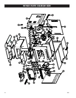
Page 26: ...26 USSC REPAIR PARTS DIAGRAM 6039...
Page 31: ...USSC 31 Notes...


