


170761-UIM-B-0406
Unitary Products Group
11
Wiring Related Fault Codes
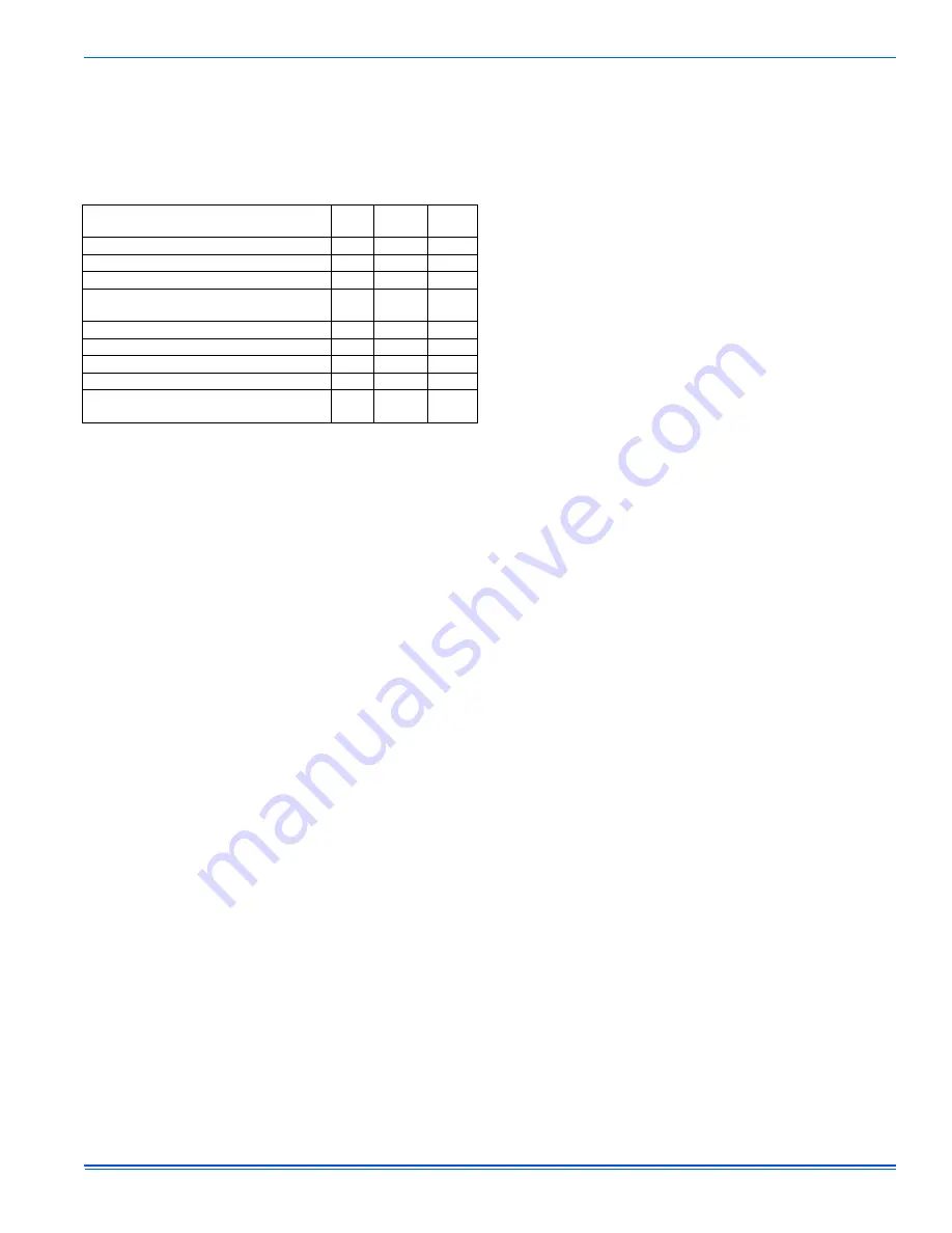
Table 8 shows the faults that the control can detect when a problem is
present with the system wiring or jumper configurations. The control
displays this type of error by flashing LED1 (Red) and energizing LED2
(Green) constantly. These faults typically occur when the heat pump is
first installed or when a system component such as the room thermostat
or indoor unit is replaced or rewired.
FAULT CODE MEMORY
Displaying Stored Fault Codes
The control will store up to five fault codes in memory. If more than five
faults occur, the five most recent fault codes will remain in memory. The
stored faults can be displayed by depressing the LAST ERROR push-
button for one to five seconds while no thermostat inputs to the control
are energized. See Figures 10 and 13 for the location of the pushbut-
ton. Since some room thermostats energize the O signal even when not
calling for compressor operation, turn the room thermostat to the SYS-
TEM OFF setting when displaying fault codes.
When the LAST ERROR pushbutton is depressed and released, the
control will display the stored fault codes beginning with the most
recent. The control will display the most recent fault code, pause two
seconds, and display the next fault code. The control will display the
stored error codes and then return to the normal LED status display
mode. The stored fault codes can be displayed again by depressing the
pushbutton again. When the control displays the fault codes with the
onboard LED’s, it will also energize the X/L output with the correspond-
ing flash code. The X/L output signal can be observed at the room ther-
mostat or at the control using a 24VAC LED test device connected to
the X/L terminal.
If the control has no fault codes stored in memory, it will flash both
LED’s twice simultaneously. If a thermostat signal is energized while the
control is displaying the stored error codes, the control will stop display-
ing the stored error codes and resume normal operation.
Clearing Fault Code Memory
Once the stored fault codes have been displayed and recorded, the
installer should clear the stored fault codes from the control’s memory.
This practice will enable better troubleshooting and diagnosis of system
problems. If the stored fault codes are not cleared after the cause of the
problem has been resolved, a service technician doing a later service
call may not know that the fault codes in the memory were caused by a
problem that has already been fixed. The technician may waste time
trying to fix a condition that no longer exists. Therefore, it is very impor-
tant to always clear the fault code memory after the unit is installed and
running properly following a service call.
IMPORTANT: Always clear the fault code memory after resolving the
condition that caused the fault code.
To clear the fault code memory, depress the LAST ERROR pushbutton
for longer than 5 seconds. The control will flash both LED’s three times
to indicate that the memory has been cleared. To confirm that the mem-
ory has been cleared, depress the LAST ERROR pushbutton for one to
five seconds. The control will flash both LED’s twice to indicate that no
faults are stored in memory.
LOCKOUT MODES
Soft Lockout
The control will cause a soft lockout during the following conditions.
Detailed descriptions of the conditions required for the control to enter
the soft lockout mode are contained in other sections of this document.
1.
High-pressure switch
a.
Two openings within six hours
2.
Low-pressure switch
a.
One opening of the switch for more than five seconds except
under certain conditions.
3.
High discharge temperature (with optional discharge sensor)
a.
Temperature reading exceeds 263F
4.
Low discharge temperature (with optional discharge sensor)
a.
Temperature reading does not reach 90F following timer expi-
ration under certain conditions.
During the soft lockout mode, the control will do the following.
1.
De-energize the compressor
2.
If in heating mode, the control will energize auxiliary heat as if the
outdoor ambient temperature was below the LTCO setting.
3.
Energize the LED and X/L outputs with the appropriate flash codes
4.
Store the appropriate fault code in memory.
The control will reset the soft lockout condition when any of the follow-
ing occur following removal of the fault condition.
1.
Power is cycled to the R or Y1 inputs of the control. This will cause
the soft lockout condition to be reset when the thermostat is satis-
fied or when the thermostat is set to SYSTEM OFF and back to
HEAT or COOL mode.
2.
The TEST terminals are shorted for more than two seconds.
When the soft lockout condition is reset, the control will stop displaying
the fault code and will respond to thermostat inputs normally.
Hard Lockout
If four soft lockouts occur within a twelve-hour period, the control shall
cause a hard lockout condition. These soft lockouts can be caused by
the same or different conditions. The control will function in the same
way during soft and hard lockout conditions. The difference is in the
requirements for resetting the lockout condition. The control will reset
the hard lockout condition when any of the following occur following
removal of the fault condition.
1.
Power is removed from the R input of the control.
2.
The TEST terminals are shorted for more than two seconds.
A hard lockout condition will not be reset when the thermostat is satis-
fied or when the thermostat is set to SYSTEM OFF and back to HEAT
or COOL mode. Power (24 VAC) to the control must be removed and
reapplied.
When the hard lockout condition is reset, the control will de-energize
the LED and X/L outputs and respond to thermostat inputs normally.
Wiring or Setting Related Lockouts
The control will not operate the compressor when the following faults
occur. These faults can be reset using the same methods used to reset
a soft lockout. However, two occurrences of these faults will not cause a
hard lockout condition.
1.
Presence of Y2 thermostat signal without Y1.
2.
Shorted discharge sensor input
3.
Shorted bonnet sensor
4.
Shorted or open liquid line or outdoor ambient sensor
5.
Defrost curve jumper error
If a compressor wiring error is detected, the control will not operate the
compressor. Once the compressor wiring error has been detected,
power (24 VAC) must be cycled to the control for the control to sense
the wiring change and clear the lockout condition.
TABLE 8: Wiring Related Fault Codes
Description
LED1
(Red)
LED2
(Green)
X/L
Wiring Related Faults
Compressor Contactor Miswire
1
ON
4
Y2 present without Y1
2
ON
4
Y1 and W present without Y2 in
two stage mode
3
ON
4
O signal received in AC mode
4
ON
4
W signal received in AC mode
5
ON
4
W and O signal received in AC mode
6
ON
4
W and O signal received in HP mode
7
ON
4
Defrost Curve Jumper Error (Invalid jumper
setting preventing compressor operation)
8
ON
4


