


278806-BIM-A-1106
26
Unitary Products Group
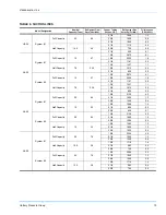
UNIT CONTROL BOARD OPTION SETUP
OPTION BYTE SETUP
•
Enter the Option Setup mode by pushing the
OPTION SETUP / STORE button, and holding it for
at least 2 seconds.
•
The green status LED (Option Byte) will be turned
on and the red status LED (Heat Delay) is turned
off.
•
The 4 LED will then show the status of the labeled
option
Low Ambient Lockout
.
•
Press the UP or Down button to change the LED
status to correspond to the desired Option Setup.
•
To save the current displayed value, push the
OPTION SETUP / STORE button and hold it for at
least 2 seconds. When the value is saved, the
green LED will flash a few times and then normal
display will resume.
NOTE:
While in either Setup mode, if no buttons are
pushed for 60 seconds, the display will revert
to its normal display, exiting the Option Setup
mode.
When saving, the control board only
saves the parameters for the currently dis-
played mode (Option Byte or Heat Delay).
(Heat Delay not applicable on these units.)
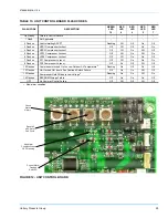
CONDENSER FAN OPERATION
These condensing units are factory equipped with fan
cycling switches to regulate system head pressure.
When outdoor ambient conditions are cool, the head
pressure of any air conditioning system may drop too
low for optimal performance. These condensing units
maximize system performance in a variety of ambient
conditions by incorporating fan cycling switches to
maintain proper system head pressure.
On these condensing units, the condenser fans of a
given system are powered when compressor one is
energized. Fan one will start immediately upon a call
for first stage cooling. However, fan two is equipped
with a fan cycling switch and will not start until the sys-
tem head pressure reaches 280 psig. Condenser fan
two will operate until the system head pressure drops
below 180 psig where the fan cycling switch will shut
the fan down. The unit will continue to operate con-
denser fan one until the system head pressure reaches
280 psig at which time condenser fan two will restart.
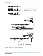
See Fan Orientation on page 26 Figure 13.
These 4-pipe condensing units can also be used with
two appropriately sized indoor units. In this case, each
indoor unit will have it’s own thermostat. One thermo-
stat will connect to “Y1” and “Y2” on the Simplicity™
control board and the other will connect to “Y3” and
“Y4”.
OPERATION WITH A TWO-STAGE THERMOSTAT
If the total system is to be controlled with a 2-stage
thermostat (HF-25):
1.
Terminals Y1 and Y2 of the Simplicity™ control
board controlling system one, should be connected
to stage one and two of the thermostat.
OPERATION WITH A FOUR-STAGE THERMOSTAT
If the total system is to be controlled with a 4-stage
thermostat (HL-30, HL-40 and HL-50):
1.
Terminals Y1 and Y2 of the Simplicity™ control
board controlling system one, should be connected
to stage one and two of the thermostat.
2.
Terminals Y3 and Y4 of the Simplicity™ control
board controlling system two, should be connected
to stage three and four of the thermostat.
SECURE OWNER'S APPROVAL
When the system is functioning properly, secure the
owner's approval. Show him the location of all discon-
nect switches and the thermostat. Teach him how to
start and stop the unit and how to adjust temperature
settings within the limitations of the system.
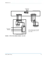
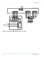
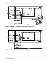
FIGURE 13 - FAN ORIENTATION CONTROL BOX
END