


278806-BIM-A-1106
24
Unitary Products Group
COOLING SEQUENCE OF OPERATION
When the thermostat calls for the first stage of cooling,
the low-voltage control circuit from the “R” to “Y1” and
“G” is completed. The Simplicity™ control board acti-
vates the first stage of cooling by energizing compres-
sor one and both condenser fans of system one. After
completing the specified fan on delay for cooling, the
Simplicity™ control board will energize the indoor
blower motor.
When the thermostat calls for the second stage of cool-
ing, the low-voltage control circuit from “R” to “Y2” is
completed. The control board will energize compressor
two.
If there is an initial call for both stages of cooling, the
Simplicity™ control board will delay energizing com-
pressor two by 30 seconds in order to avoid an exces-
sive power rush.
When the thermostat calls for the third stage of cooling,
the low-voltage control circuit from the “R” to “Y3” is
completed. The Simplicity™ control board activates the
third stage of cooling by energizing compressor three
and both condenser fans of system two.
When the thermostat calls for the fourth stage of cool-
ing, the low-voltage control circuit from “R” to “Y4” is
completed. The control board will energize compressor
four.
Once the thermostat has been satisfied, the
Simplicity™ control board will de-energize Y1, Y2, Y3
and Y4. If the compressors have satisfied their
minimum run times, the compressors and condenser
fans are de-energized. Otherwise, the unit operates
each cooling stage until the ASCD has elapsed. Upon
the completion of first stage cooling, the blower is
stopped following the completion of the fan off delay
cycle.
FLASH CODES
Various flash codes are utilized by the unit control
board (UCB) to aid in troubleshooting. Flash codes are
distinguished by the short on and off cycle used
(approximately 200ms on and 200ms off). To show
normal operation, the control board flashes a 1 second
on, 1 second off "heartbeat" during normal operation.
This is to verify that the UCB is functioning correctly.
Do not confuse this with an error flash code. To prevent
confusion, a 1-flash, flash code is not used.
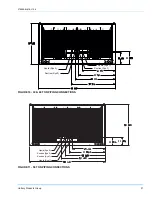
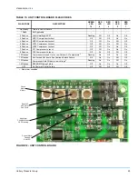
Alarm condition codes are flashed on the UCB lower
left Red LED, See Figure 12. While the alarm code is
being flashed, it will also be shown by the other LEDs:
lit continuously while the alarm is being flashed. The
total of the continuously lit LEDs equates to the number
of flashes, and is shown in the table. Pressing and
releasing the LAST ERROR button on the UCB can
check the alarm history. The UCB will cycle through the
last five (5) alarms, most recent to oldest, separating
each alarm flash code by approximately 2 seconds. In
all cases, a flashing Green LED will be used to indicate
non-alarm condition.
In some cases, it may be necessary to "zero" the
ASCD for the compressors in order to perform trouble-
shooting. To reset all ASCDs for one cycle, press and
release the UCB TEST/ RESET button once.
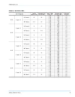
Flash codes that do and do not represent alarms are
listed in Table 13.