Unitary products group HA 300 Installation Manual Download Page 6

035-18575-001-A-1102

6

Unitary Products Group

INSTALLATION

LIMITATIONS

These units must be installed in accordance with all
national and local safety codes. If no local codes apply,
installation must conform to the appropriate national
codes. Units are designed to meet National Safety
Code Standards. If components are to be added to a
unit to meet local codes, they are to be installed at the
dealer's and/or the customer's expense.
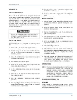
LOCATION

Use the following guidelines to select a suitable loca-
tion for both the condensing unit and the evaporator.

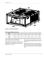
TABLE 1: PHYSICAL DATA

Model

HA/HB

Compressor

*

Condenser

Unit Weight

(Lbs.)

Charge, R-22

Fan (Propeller)

Fan Motor Coil (Copper Tube-Aluminum Fin)

Nominal

Capacity

(tons)

Capacity

Stages

Qty. Dia.

Pitch

Deg.

Nom.

CFM

RPM

HP

Face

Area

(Ft.

)

Rows

Deep

Coil

Width

(In.)

Tube

OD

(In.)

Fins

per

inch

Ship-

ping

Opera-

tion

Operation

(Lbs.-Oz.)

Holding

(Lbs.)

300

25

2

4

24

34

25200

1425

1.50

50

2

60

3/8

16

1598

1648

50.3

1.0

360

System 1

15

2

2

24

36

12600

1.50

25

60

1710

1770

31.5

1.0

System 2

15

2

2

24

36

12600

1.50

25

60

31.5

480

System 1

20

2

2

30

22

16550

1.50

32.5

78

1941

2017

38.1

1.0

System 2

20

2

2

30

22

16550

1.50

32.5

78

38.1

600

System 1

25

2

2

30

22

19725

1.50

52

78

2450

2543

47.3

1.0

System 2

25

2

2

30

22

19725

1.50

52

78

47.3

*.

All compressors are Copeland Scrolls.

†.

One of the fan motors is controlled by a pressure switch and will not operate until system pressure reaches 280 psig and drops
below 180 psig.

‡.

The total operating charge of the condensing unit, matching indoor unit and 25 feet of interconnecting piping.

TABLE 2: UNIT APPLICATION DATA

Voltage Variation

*

Min. / Max.

*.

Utilization range “A” in accordance with ARI Standard
110.

380/415-3-50

342/456

Ambient Air on Condenser Coil

Min. /Max.

40°F/125°F

†.

These units can operate in an ambient temperature of
125°F providing the wet bulb temperature of the air
entering the evaporator coil does not exceed 67°F.

Suction Pressure at Compressor and

Corresponding Temp. at Saturation

Min. / Max.

57.5 psig / 92.6 psig

32.0 ºF / 55.0 ºF

Summary of Contents for HA 300

Page 1: ...intended to clarify or make the installation easier Cautions are given to prevent equipment damage Warnings are given to alert installer that personal injury and or equipment dam age may result if in...

Page 2: ...ES 23 CONDENSER FAN OPERATION 23 OPERATION WITH A TWO STAGE THERMOSTAT 24 OPERATION WITH A FOUR STAGE THERMOSTAT 24 SECURE OWNER S APPROVAL 24 MAINTENANCE 24 CLEANING CONDENSER SURFACE 24 LUBRICATION...

Page 3: ...ER OF GRAVITY INCHES 7 4 MINIMUM CLEARANCES 8 5 ELECTRICAL DATA 10 6 SUCTION LINES 13 7 LIQUID LINES 14 Tbl Pg 8 R 22 LINE CHARGE 14 9 UNIT DIMENSIONS INCHES 17 10 PIPING AND ELECTRICAL CONNECTION SIZ...

Page 4: ...egory H Air Conditioner Split System A Product Identifier A R 22 Standard Efficiency 2 Pipe B R 22 Standard Efficiency 4 Pipe 300 Nominal Cooling Capacity MBH 300 25 Ton 360 30 Ton 480 40 Ton 600 50 T...

Page 5: ...and operation of the basic condensing unit For information on the installation and operation of the evaporator blower units refer to instruction Form No 035 18496 000 All accessories come with a sepa...

Page 6: ...50 50 2 60 3 8 16 1598 1648 50 3 1 0 360 System 1 15 2 2 24 36 12600 1 50 25 60 1710 1770 31 5 1 0 System 2 15 2 2 24 36 12600 1 50 25 60 31 5 480 System 1 20 2 2 30 22 16550 1 50 32 5 78 1941 2017 3...

Page 7: ...The beams should 1 be positioned per pendicular to the roof joists 2 Extend beyond the dimensions of the section to distribute the load on the roof 3 Be capable of adequately supporting the con centra...

Page 8: ...e compressor out through the top of the unit RIGGING Exercise care when moving the unit Do not remove any crating until the unit is near the place of installation When preparing to move the unit alway...

Page 9: ...producing a high noise level the scroll is misphased CONTROL WIRING Route the necessary low voltage control wires from the Simplicity control board to the thermostat and also from the low voltage cond...

Page 10: ...ding charge A filter drier MUST be field installed in the liquid line of every system to prevent dirt and moisture from damag ing the system Properly sized filter driers are shipped with each condensi...

Page 11: ...e sealing disk and prepare the joint for connections of the main lines Connect the lines while maintaining a flow of Nitrogen from the liquid line valve service port through the evaporator back to the...

Page 12: ...dehydration charge the required weight of liquid refrigerant into the liquid access connection After refrigerant flow slows start the compressor and continue to charge refrigerant gas through the suct...

Page 13: ...System 2 Full Capacity 15 47 1 3 8 3529 14 3 1 5 8 2498 6 3 2 1 8 1439 1 7 Half Capacity 7 5 23 5 1 3 8 1765 4 3 1 5 8 1249 1 9 2 1 8 720 0 5 HB480 System 1 Full Capacity 20 64 1 5 8 3402 11 1 2 1 8...

Page 14: ...9 1 1 8 141 1 1 Half Capacity 10 32 5 8 174 6 2 7 8 120 1 0 1 1 8 70 0 3 System 2 Full Capacity 20 64 5 8 348 22 1 7 8 240 3 9 1 1 8 141 1 1 Half Capacity 10 32 5 8 174 6 2 7 8 120 1 0 1 1 8 70 0 3 HB...

Page 15: ...035 18575 001 A 1102 Unitary Products Group 15 FIGURE 3 FIELD WIRING DIAGRAM HA 300 UNIT POWER SUPPLY 380 415 3 50 POWER SUPPLY 380 415 3 50...

Page 16: ...035 18575 001 A 1102 16 Unitary Products Group FIGURE 4 FIELD WIRING DIAGRAM HB 360 480 600 UNITS POWER SUPPLY 380 415 3 50 POWER SUPPLY 380 415 3 50...

Page 17: ...nit from the left or right side Electrical connections for power and control wiring is made from the front of the unit left of the electrical con trol box access See Tables 10 11 and 12 and Figures 6...

Page 18: ...75 001 A 1102 18 Unitary Products Group FIGURE 6 25 30 40 TON POWER AND CONTROL WIRING CONNECTIONS Control Wiring Power Wiring FIGURE 7 50 TON POWER AND CONTROL WIRING CONNECTIONS Control Wiring Power...

Page 19: ...12 CONTROL WIRING 7 8 HOLE TABLE 11 PIPING AND ELECTRICAL CONNECTION SIZES 30 40 50T INCHES CONNECTION ENTRY SIZE SUCTION LINE SYS 1 1 5 8 OD LIQUID LINE SYS 1 7 8 OD SUCTION LINE SYS 2 1 5 8 OD LIQUI...

Page 20: ...A 1102 20 Unitary Products Group FIGURE 9 30 40 TON PIPING CONNECTIONS Liquid Sys 2 Suction Sys 2 Liquid Sys 1 Suction Sys 1 FIGURE 10 50 TON PIPING CONNECTIONS Liquid Sys 2 Suction Sys 2 Liquid Sys 1...

Page 21: ...lectrical wire laying against a hot refrigerant line INITIAL START UP 1 Supply power to the unit through the disconnect switch at least 8 hours prior to starting the com pressor 2 Move the system swit...

Page 22: ...lock out the associated compressor and flash an error code see Table 12 An ambient air switch will lock out mechanical cooling at 40 F In order to operate the unit in ambient temper atures below 40 F...

Page 23: ...rol will separate the flash codes with a 2 sec ond off delay between flash codes Under normal oper ation the control will flash the LED at a rate of 1 second on and 1 second off This will be the Heart...

Page 24: ...be connected to stage one and two of the thermostat 2 Terminals Y3 and Y4 of the Simplicity control board controlling system two should be connected to stage three and four of the thermostat SECURE OW...

Page 25: ...with the TXV s left to the factory setting If the TXV s have been adjusted in the field the chart above may no longer apply FIGURE 13 30 TON CHARGING CHART 30 ton Charging Chart 100 150 200 250 300 35...

Page 26: ...with the TXV s left to the factory setting If the TXV s have been adjusted in the field the chart above may no longer apply FIGURE 15 50 TON CHARGING CHART 50 ton Charging Chart 100 150 200 250 300 35...

Page 27: ...035 18575 001 A 1102 Unitary Products Group 27 FIGURE 16 25 TON CONDENSER UNIT WIRING DIAGRAM 380 415 3 50...

Page 28: ...035 18575 001 A 1102 28 Unitary Products Group FIGURE 17 30 or 40 TON CONDENSING UNIT WIRING DIAGRAM 380 415 3 50...

Page 29: ...035 18575 001 A 1102 Unitary Products Group 29 FIGURE 18 50 TON CONDENSER UNIT WIRING DIAGRAM 380 415 3 50...

Page 30: ...035 18575 001 A 1102 30 Unitary Products Group...

Page 31: ...035 18575 001 A 1102 Unitary Products Group 31...

Page 32: ...o change without notice Printed in U S A 035 18575 001 A 1102 Copyright by Unitary Products Group 2002 All rights reserved Supersedes 035 18575 000 A 0402 Unitary 5005 Norman Products York OK Group Dr...

Reviews: