035-18877-001-B-0203
Unitary Products Group
11
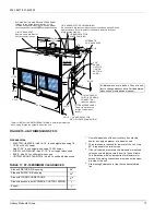
Before brazing the refrigerant lines to these connections,
remove the short panel from the unit frame and slide it (along
with the grommets) onto the refrigerant lines. After the brazed
joints have cooled, slide the panel back into place and secure
it to the unit frame.
NOTE:
These units can only be piped from one side of the
unit.
EXPANSION VALVE BULB
The expansion valve bulb must be fastened in a 10 or 2
o'clock position to the suction line outside the cabinet after
the piping connections have been made.
Use the clamps provided with the valve to secure the bulb in
position. Bulb must be insulated with armaflex or mastic to
assure proper operation.
NOTE:
These coils can only be piped from one side of the
unit.
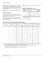
TABLE 5: ELECTRICAL DATA - FF-10
Blower
Motor HP
Power Supply
FLA
Max. Fuse
Size
1
AMPS
1.
Dual element, time delay fuses.
2
208-3-60
7.5
15
230-3-60
6.8
15
460-3-60
3.4
15
Note: Refer to Form 035-16602-001 for electrical data on units equipped
with an electric heat accessory.
TABLE 6: ELECTRICAL DATA - UNITS WITH ELECTRIC HEAT
Model Basic Unit
1
Nominal Heater
KW
2
Power Supply
Voltage
3
Full Load Amps
Total Ampacity,
Amps
Max. Fuse Size
4
,
Amps
Heater
Blower Motor
120
10
208
20.8
7.5
35.4
35
230
24.1
6.8
37.3
40
460
12.0
3.4
19.2
20
16
208
33.3
7.5
51.1
50
230
38.5
6.8
54.6
60
460
19.2
3.4
26.1
30
26
208
54.1
7.5
77.1
80
230
62.5
6.8
83.4
90
460
31.3
3.4
41.7
45
36
208
74.9
7.5
103.2
110
230
86.6
6.8
112.2
125
460
43.3
3.4
56.1
60
1.
Units with an electric heat accessory will always be wired for a single power supply.
2.
Refer to the HEATING CAPACITY table for the actual KW and MBH ratings of each heater at the different voltages.
3.
All voltages are for 3-phase, 60 hertz operation.
4.
Inverse time circuit breakers may be used in lieu of dual element, time delay fuses.


