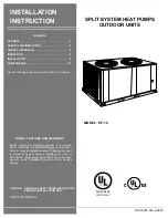
background image

INSTALLATION 
INSTRUCTION

CAUTION:

READ ALL SAFETY GUIDES BEFORE YOU 
BEGIN TO INSTALL YOUR UNIT.

SAVE THIS MANUAL

MODEL:  EF-10

O

O

O

O

O

208/230/460
VOLT ONLY

SPLIT-SYSTEM HEAT PUMPS

OUTDOOR UNITS

035-18550-001-A-0902

CONTENTS

GENERAL  . . . . . . . . . . . . . . . . . . . . . . . . . . . . . . . . . . . .4

SAFETY CONSIDERATIONS  . . . . . . . . . . . . . . . . . . . . .4

AGENCY APPROVALS . . . . . . . . . . . . . . . . . . . . . . . . . .4

INSPECTION . . . . . . . . . . . . . . . . . . . . . . . . . . . . . . . . . .4

INSTALLATION   . . . . . . . . . . . . . . . . . . . . . . . . . . . . . . .5

MAINTENANCE   . . . . . . . . . . . . . . . . . . . . . . . . . . . . . .21

See the following page for a complete Table of Contents.

NOTES, CAUTIONS AND WARNINGS

Installer should pay particular attention to the words:

NOTE

CAUTION

, and 

WARNING

. Notes are intended to

clarify or make the installation easier. Cautions are given
to prevent equipment damage. Warnings are given to
alert installer that personal injury and/or equipment dam-
age may result if installation procedure is not handled
properly.

Summary of Contents for EF-10

Page 1: ...OVALS 4 INSPECTION 4 INSTALLATION 5 MAINTENANCE 21 See the following page for a complete Table of Contents NOTES CAUTIONS AND WARNINGS Installer should pay particular attention to the words NOTE CAUTI...

Page 2: ...RT UP 17 CRANKCASE HEATER 17 PRE START CHECK 17 INITIAL START UP 18 PHASING 18 OPERATION 18 GENERAL 18 SYSTEM SEQUENCE OF OPERATION 18 COOLING OPERATION 18 HEATING OPERATION 19 DEFROST CYCLE 20 OPERAT...

Page 3: ...Split System E Heat Pump Split System F Product Identifier F R 22 Standard Efficiency 2 Pipe 10 Nominal Cooling Capacity MBH 07 7 1 2 Ton 10 10 Ton C Heat Type C Cooling Only 00 Nominal Heating Capac...

Page 4: ...tion proce dure is not handled properly REFERENCE This instruction covers the installation of the outdoor unit For information on the matching indoor see PN 035 18877 001 All accessories come with a s...

Page 5: ...ans Quantity 2 Diameter In No Blades 24 3 Nominal CFM 7830 Fan Motors2 HP 3 4 RPM 1100 Coil Face Area Sq Ft 36 11 Rows Deep x Rows High 2 x 40 Finned Length In 130 Tube Copper OD inches 3 8 Fins Alumi...

Page 6: ...concrete slab with footers that extend below the frost line is recommended The slab should not be tied to the building foundation because noise and vibration will telegraph into the building A unit c...

Page 7: ...m either side Remove the nesting brackets from the four corners on top of the unit All screws that are removed to take these brackets off must be replaced on the unit Do not use straps under the unit...

Page 8: ...Piping and Access Panels 30 Left Side 24 Right Side 24 Rear 24 Bottom2 2 Adequate snow clearance must be provided during winter oper ation 0 Do not permit overhanging structures or shrubs to obstruct...

Page 9: ...to Figure 5 for typical field wiring PHASING Scroll compressors operate in one direction only if a three phase scroll compressor is experiencing Low amperage draw Similar discharge and suction pressu...

Page 10: ...MPACITY AMPS MAXIMUM FUSE SIZE2 AMPS MINIMUM DISCONNECT SIZE3 AMPS EF 10 2 208 230 3 60 1 42 0 239 0 2 3 4 3 0 58 5 100 100 4 460 3 60 1 19 2 125 0 2 3 4 1 6 27 2 45 45 1 The 208 230 V compressors and...

Page 11: ...or a field installed liquid line should never exceed 40 psi because the liquid refriger ant could flash before it reaches the expansion valve This flashing will not only cause erratic valve operation...

Page 12: ...h the cooling and heating cycles SERVICE VALVES These outdoor units have both vapor and liquid line service valves Both valves are shipped from the factory front seated and closed with the valve stem...

Page 13: ...lve stem should be turned to its maximum clockwise posi tion 2 Drill a small hole through the disc before unbrazing it to permit a flow of dry nitrogen through the con nection while it is being unbraz...

Page 14: ...connection on the indoor unit while maintaining a minimum flow of dry nitrogen through the liquid line the indoor coil and the hole in the vapor disc 7 Unbraze the disc on the vapor connection of the...

Page 15: ...e 1 4 turn to open its access port for reading pressure Start the compressor after 8 hours of crankcase heat turn the stem of the vapor line service valve clockwise 1 4 turn to open its service port a...

Page 16: ...glass is clear Add approximately 1 extra pound of refrigerant to assure a liquid refrigerant seal at the expansion valve under all operating condi tions Block the flow of the condenser air if necessar...

Page 17: ...rials etc 3 Have the outdoor fans been rotated manually to check for free rotation 4 Are all wiring connections tight 5 Does the available power supply agree with the nameplate data on the unit 6 Have...

Page 18: ...age draw Similar discharge and suction pressures Increased noise level then the compressor is operating in reverse To correct this condition switch any two 2 line voltage leads at the contactor Please...

Page 19: ...ALL THREE RESET METHODS DESCRIBED ABOVE A FIVE MINUTE TIME DELAY WILL TAKE PLACE AFTER THE RESET BEFORE THE UNIT WILL RESTART HEATING OPERATION 1 Reversing valve is de energized and the system will be...

Page 20: ...ATION BELOW 0 F OUTDOOR TEMPERATURE 1 At 0 F outdoor temperature the low temperature compressor cutoff thermostat 1TH contacts 1 and 3 will open de energizing contactor 1M which shuts down the compres...

Page 21: ...em performance and efficient operation If the coil is extremely dirty it may be necessary to use an industrial grade detergent and a hose to clean the fin surface LUBRICATION The outdoor fan motors ar...

Page 22: ...035 18550 001 A 0902 22 Unitary Products Group...

Page 23: ...035 18550 001 A 0902 Unitary Products Group 23...

Page 24: ...o change without notice Printed in U S A 035 18550 001 A 0902 Copyright by Unitary Products Group 2002 All rights reserved Supersedes 035 18550 000 A 0402 Unitary 5005 Norman Products York OK Group Dr...

Reviews: