UNISENSE MultiChannel UniAmp User Manual Download Page 12

12

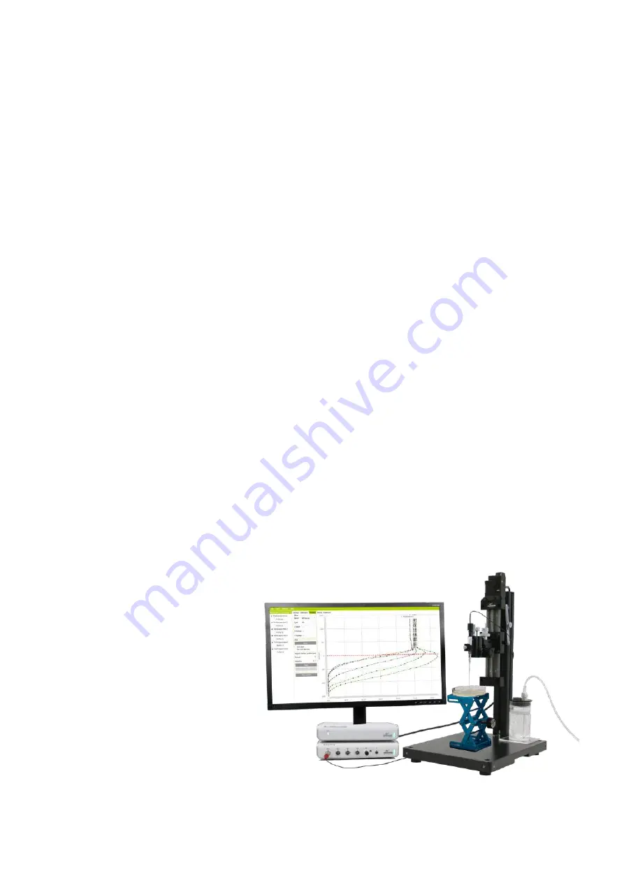
Motorized 1D profiling set-up with fx-6 UniAmp, one motor controller, 
single sensor, CAL300 and computer (not provided)

SETTING UP

The following section will describe a typical profiling set-up ⸀ 
Please consult separate manuals for the individual components for 
further details ⸀

1 ⸀  Install the Unisense SensorTrace Suite software ⸀

2 ⸀  Place the laboratory stand LS on a stable and smooth surface ⸀ 

Adjust the feet to prevent the stand from rocking ⸀ If the sample is 
not to be placed on the stand plate, the stand should be placed 
at an appropriate distance from the sample to allow space for the 
micromanipulator ⸀ 

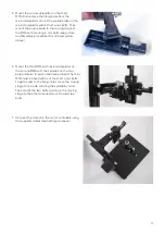
3 ⸀  Mount the micromanipulator or assembled motorized system 

(see below for instructions) on the stand with the 昀椀xation screw 

at a suitable height so that the lower side of the sensor holder is 
positioned about 12 ⸀5 cm/5” above the top of the sample, when the 
microsensor z-axis is completely retracted ⸀

4 ⸀  If motorized, connect the motor port of the motor controller to the 

motor stage(s) using the motor cable(s) ⸀

5 ⸀  Connect the the motor controller to the PC using the  USB (USB - 

mini USB) cable. In the SensorTrace Pro昀椀ling software setup screen 
each connected motor controller can be assigned to a speci昀椀c axis. 

Clicking the controller on the setup screen will cause the green light 

on the motor controller to blink for identi昀椀cation. See the SensorTrace 

Suite User Manual for details ⸀ 

6 ⸀ 

Place the microsensor ampli昀椀er(s) near the stand (0.5m/1.5ft) 

7 ⸀ 

Connect the ampli昀椀ers to the PC using the USB cable.

8 ⸀  Place the sample to be investigated under the micromanipulator

9 ⸀  Place a microsensor in the holder of the micromanipulator with the tip 

a few centimetres above the sample ⸀ Move the sensor horizontally to 
the desired location with the x- and 
y-controls ⸀ Be careful not to break the 
microsensor tip!

10 ⸀ Make measurements with the sensors 

according to the manuals for the 
sensors and software ⸀

Summary of Contents for MultiChannel UniAmp

Page 1: ...1 MICROPROFILING SYSTEM USER MANUAL...

Page 2: ...Microprofiling systeM user Manual Copyright 2023 Unisense A S Version November 2023...

Page 3: ...tionS mm33 and mm33 2 11 MOTORIZED SYSTEMS 12 SpecificationS for motor controller mc 1 mc 2 and mc 3 13 SpecificationS for motor Stage mS 15 13 motor control Button functionS 13 MICROMANIPULATOR STAND...

Page 4: ...its or for any claim by any third party arising out of the use the results of use or the inability to use this product Unisense mechanical and electronic laboratory instruments must only be used under...

Page 5: ...Further documentation and support is available at our website www unisense com CONGRATULATIONS WITH YOUR NEW PRODUCT REPLACEMENT OF SENSORS Unisense will replace sensors that have been damaged during...

Page 6: ...al profiles the micromanipulator is operated by hand For increased accuracy and automatic profiles a motorized stage and motor controller can be used This will increase microsensor positioning precisi...

Page 7: ...niAmp fx 6 or fx 3 or a picoammeter with preset polarization like the O2 UniAmp Potentiometric microsensors e g pH and Redox require a high impedance millivoltmeter like the pH Redox UniAmp or a Multi...

Page 8: ...icrosensors with a z axis precision of 10 microns The x and y axis can be manipulated with a precision of 100 microns The MM33 2 offers the possibility for simultanous positioning of two sensors It al...

Page 9: ...3D with extreme precision it all directions Motorized sensor positioning is superior to manual positioning due to a higher level of precision a longer operating distance and ease of operation A motor...

Page 10: ...sec Minimum linear speed 1 m sec Maximum axial load 5 kg 11 lbs Motor type Stepper motor Motor control button functions The Control Button on the motor housing see picture right has several functions...

Page 11: ...It consists of a pointed angular aluminum pole and its tip is pushed into the substrate to provide a robust support for micromanipulators and sensors during in situ experiments It can be used under w...

Page 12: ...sample when the microsensor z axis is completely retracted 4 If motorized connect the motor port of the motor controller to the motor stage s using the motor cable s 5 Connect the the motor controlle...

Page 13: ...unted in one of three positions centred on the Tilting Base or high or low To get access to the holes in the MS 15 back move the Stage Plate up or down using the Motor Control Button on the motor hous...

Page 14: ...14 Fig 5 Fig 6 Fig 7 Fig 8 Fig 9 Fig 4...

Page 15: ...that the motor points in the direction where the tilting plate is hinged see step 3 in the 1D assembly procedure above Move the stage plate completely down by turning the spindle joint with a nger and...

Page 16: ...MMS on the 3D arm using 4 of the long 4 mm bolts Move the moving stage on the MMS to one side by rotating the spindle by hand This will expose two of the xing holes see picture Mount the 2 bolts and...

Page 17: ...motorized system above 6 Mount the third MMS with micromanipulator on the second MMS with the spindles on the two perpendicular to each other see picture The third MMS must be xed with 4 of the short...

Page 18: ...nd stands with distilled water if salt or other corrosive material have been deposited on them Keep the micromanipulator and motor free of sand and dust WARNING Do not spray the MMS with silicone IMPO...

Reviews: