background image

Page 20

P O W E R I N G   T E C H N O L O G Y

Manual No. PM110-6500-00 rev-2a

PM110-6500-00-rev2a-0117.indd

Aspiro system can be easily mounted to a rack using the taptite screws to fasten the mounting 

brackets to the rack as shown in Figure 4-2. 

NOTE  

It is recommended to remove the rectifiers before installing the shelf to the cabinet 

or rack.


Figure 4-2 System Mounting (19” mount)

NOTE  

Mounting hardware is not supplied with the system.

4.5 Rear Connections

All cable connections for the Aspiro system are available at the rear of the system, see Figure 

4-3. 

CAUTION  

Use UL-listed power cords.

WARNING  

Before inserting signal cables into the connector, remove as little insulation 

on the cable as possible, to prevent the stranded conductor to come loose and touch any 

other conductive parts.

4

3

2

1

LOAD

+

_

+

_

+

_

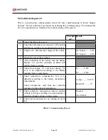
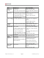
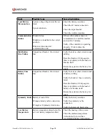
+

_

BATTERY

+

_

AC INPUT 2

AC INPUT 1

SIGNAL

CONNECTIONS

BATTERY

AC

INPUTS

DC

OUTPUTS

+

-

+

-

+

-

+

_

Figure 4-3 Rear Connections

Summary of Contents for Aspiro 2U Enclosure

Page 1: ...mber PM110 6500 00 rev2a 2017 UNIPOWER LLC All Rights Reserved PM110 6500 00 rev2a 0117 indd UNIPOWER LLC 3900 Coral Ridge Drive Coral Springs Florida 33065 USA sales unipowerco com North America 1 95...

Page 2: ...this product manual are the property of their respective trademark holders These trademark holders are not affiliated with UNIPOWER LLC or our products They do not sponsor or endorse our products LIMI...

Page 3: ...BD 11 2 4 4 Rectifier Module 12 Chapter 3 System Safety 13 3 1 Safety Warnings and Guidelines 13 3 1 1 System Markings 13 3 1 2 Safety Recommendations 13 3 1 3 Installation Warning 13 3 1 4 Electrical...

Page 4: ...missioning Overview 28 5 2 Tools and Test Equipment 28 5 2 1 Tools List 28 5 2 2 Test Equipment 28 5 3 Preparation 28 5 4 Commissioning procedure 29 5 5 Test of output voltage 30 5 5 1 Float charge U1...

Page 5: ...l Connection Detail 24 Figure 4 7 Load and Battery Connections Rear View 24 Figure 4 8 Battery Cable Detail 25 Figure 4 9 Symmetry Measurement for illustration only 26 Figure 4 10 Temperature Sensor C...

Page 6: ...nstallation and installing the power system This manual assumes that the technician has an understanding of power systems in general and understands safety procedures for working around AC and DC volt...

Page 7: ...r XPGe12 48 1200 W Rectifier DB22 Distribution Drawer 4 x load 1 x battery 1 4 Feedback Support For technical support or feedback please visit http www unipowerco com contact Alternatively email techn...

Page 8: ...de wide input operating range wide operating temperature full self protection and three LEDs for immediate rectifier status indication The power system can be managed locally through messages and alar...

Page 9: ...Modem using PowCom software Visual Indication Green LED System On Yellow LED Message s Red LED Alarm s Analog Inputs 12 x voltage inputs range 0 100VDC used for symmetry inputs Analog Outputs 4 x pot...

Page 10: ...rear to front Protection Short circuit proof automatic current limiting selective shutdown of modules at excessive output voltage Alarms High output voltage shutdown Low voltage module failure LED In...

Page 11: ...f 2 4 2 DC Distribution DC Distribution consists of 1 x 40A battery and 4 x 15A load breakers The distribution unit is designed for switching the battery and load on and off The battery and load break...

Page 12: ...monitoring through an internal microprocessor giving up to the second updates to the system controller and companion rectifiers This guarantees tightly controlled load sharing among rectifiers and pr...

Page 13: ...s and aisles Tools present a tripping hazard in confined areas Keep the system area clear and dust free during and after the installation Always know the location of emergency shut off switches in cas...

Page 14: ...endations for working near the Power System WARNING Observe low voltage safety precautions before attempting to work on the system when power is connected Potentially lethal voltages are present withi...

Page 15: ...dential installation This equipment generates uses and can radiate radio frequency energy and if not installed and used in accordance with the instructions may cause harmful interference to radio comm...

Page 16: ...burn these batteries may result in an explosion and the generation of toxic fumes Should a lead acid battery suffer damage it must be moved into a well ventilated area Contact with the corrosive flui...

Page 17: ...that may be permanently damaged by the discharge of electrostatic charges encountered in routine handling testing and transportation 3 2 4 Traceability CAUTION Units are labeled with permanently atta...

Page 18: ...duction This chapter provides detailed instructions for installing the Aspiro 1U Power System 4 2 Unpacking Check that the received equipment is in accordance with the packing list Ensure that the cab...

Page 19: ...to be sufficient clearance at the front for rectifier installation and at the rear for connections When using side mains and DC connectors sufficient space should be allowed for access in this case 1...

Page 20: ...em Mounting 19 mount NOTE Mounting hardware is not supplied with the system 4 5 Rear Connections All cable connections for the Aspiro system are available at the rear of the system see Figure 4 3 CAUT...

Page 21: ...ed on the right rear side of the system shown in Figure 4 4 2 1 _ _ BATTERY _ AC INPUT 2 AC INPUT 1 BATTERY AC INPUTS UTS _ Figure 4 4 Mains Connection viewed from rear NOTE AC inputs are independent...

Page 22: ...Voltage Inputs 1 12 can be reconfigured as external analog inputs The pin description detail for all signal connections is shown in Figure 4 5 Alarm connections are Form C relays and can be monitored...

Page 23: ...18 0V Sense 5V 0V Sense 5V Battery Temp Ambient Temp Alarm 4 C Alarm 4 NC Alarm 4 NO Alarm 1 C Alarm 1 NC Alarm 1 NO Alarm 2 C Alarm 2 NC Alarm 2 NO Alarm 3 C Alarm 3 NC Alarm 3 NO Multipurpose 1 Mult...

Page 24: ...nsert the connector back into the terminal block Maximum cable size is 1 5mm2 Maximum torque required for tightening the screw is 0 25Nm Figure 4 6 Signal Connection Detail 4 5 4 DC Load Connections L...
Page 25: ...en to the system Battery cable ZLH 00254 01 is custom design for the Aspiro enclosure connections are available at the rear of the system adjacent to the load connections see Figure 4 8 To connect 1 C...
Page 26: ...t is not delivered with the system NOTE See Figures 4 5 and 4 6 for connection to the system 4 5 7 Temperature Sensor Connection Temperature sensor connections for supervising battery temperature and...

Page 27: ...P O W E R I N G T E C H N O L O G Y Manual No PM110 6500 00 rev 2a PM110 6500 00 rev2a 0117 indd Temp Sensor Figure 4 10 Temperature Sensor Connection NOTE See Figures 4 5 and 4 6 for connection to th...

Page 28: ...SAFETY REGULATIONS If there are any difficulties in increasing the voltage to alarm level the alarm level can be adjusted to a lower level 5 2 Tools and Test Equipment 5 2 1 Tools List The essential...

Page 29: ...If the voltage is negative change over the connection of the gray and black battery cables to the batteries 5 Plug in the AC power cord 6 Plug in the rectifier modules starting from the leftmost posi...

Page 30: ...ise ordered the default output voltage is factory preset to 53 5V The total voltage has to be in accordance to the number of battery cells Please verify number of cells and the battery manufacturers r...

Page 31: ...o make sure that it is in accordance with the battery manufacturer s recommendations For systems with battery temp probe cable Temperaturecompensation is factory preset Check that the temp probe is ac...

Page 32: ...AC Input 1 VAC AC Input 2 VAC 4 Mount the rest of the rectifiers 5 After connection of the battery turn the battery breaker on and the controller if fitted will read the battery current 6 Check float...

Page 33: ...g This troubleshooting chapter helps to determine the cause of the problem and suggests possible repair solutions If the first step of the recommendation does not solve the problem continue to the nex...

Page 34: ...igh Voltage AC voltage rises above the set limit Verify the High AC voltage limit Verify the AC Input voltage Module Failure Faulty module AC OFF on a single rectifier if more than one rectifier is in...

Page 35: ...fy there is no short circuit in load cabling Reset the breaker if it trips again there is a problem with the load or a breaker itself Return the system to the factory for repair Battery Fuse Failure T...

Page 36: ...emperature is greater than 60 C Verify the temperature probe connection Verify the internal external temperature via controller front panel Replace the faulty probe with a new one Identify the root ca...

Page 37: ...blanking panel using a flat or Pozidrive screwdriver as appropriate see Figure 7 1 Figure 7 1 Unlocking the Controller Removing the Blanking Panel 2 If removing a controller out it of the shelf as sh...

Page 38: ...XR04 48 XR08 48 Replacement To replace an XR04 48 or XR08 48 rectifier follow the steps below 1 Loosen the screw on the rectifier front panel using a screwdriver Figure 7 3 1 2 Push the release sprin...

Page 39: ...t Figure 7 4 1 2 Once unlocked pull both handles down and remove the rectifier from the slot Figure 7 4 2 3 Replace rectifier Make sure that the rectifier handle is in OPEN position forms 35 40 angle...

Page 40: ...8 7 Alarm4 NC Alarm3 NO Alarm3 C Alarm4 NO Alarm4 C Alarm3 NC 15 14 13 Digital In2 Digital Out1 Digital In1 18 17 16 V sys V sys Digital Out2 X9 X10 F1 F1 F2 F3 F4 F2 F3 F4 8 7 6 5 4 3 2 1 X6 2 1 Bat...

Page 41: ...EAR VIEW EXTERNAL CABLES ARE NOT INCLUDED IN 111 6500 00 SYSTEM CUSTOMER SPECIFIED CABLE UNIPOWER PN 262 8700 01 VENDOR TE 640713 2 UNIPOWER PN 262 8700 10 VENDOR TE 770246 3 FOR 12 10 GAUGE WIRE UNIP...

Reviews: