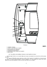
The connection between the devices along CAN interface is executed by parallel connection of two-
wire line as it should be observed the requirement potential “L” and “H” not to be crossed. The maximum
distance between the end devices should be 1200 m.
The recommended connecting wire cross section should not be less than:
♦
Up to 500
м
- connecting wire 2
х
0.5 mm
2
♦
Up to 1000
м
- connecting wire 2
х
1.0 mm
2
For bigger distances or operation in environment with electromagnetic radiation it is recommended
the wire to be double-core or shielded. If the wire is shielded, the shield should be connected only in one
end to “earth” terminal on the respective fire control panel or repeater
Regardless the line length a jumper should be installed to the first and the last device to terminate the
line by 120 ohms. The jumper (J)
should be removed from all other devices (Drawing 2).
First device
Last device
Drawing 2
2.2.2. Connection of the repeater to PC
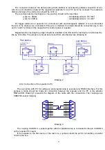
The connection with PC for setting up and programming is executed via RS232 interface. For this
purpose a cable should be made for connection between the repeater and the PC or the adaptor
RS232-USB. Drawing 3 presents the diagram of the cable with the connections. The couplings are
CANON 9-socket (female).
1
6
2
7
3
8
4
9
5
DB9F
1
6
2
7
3
8
4
9
5
DB9F
Drawing 3
The coupling CANON 9 – socket together with the installed wires is connected to the pin CANON 9
on the repeater PC board.
If the repeater is the first device or the last one, a jumper should be put for connecting a resistor
120
Ω
to the line.
3

