9
INSTALLATION
(continued)
1.
Unpack the sewing machine and the accessories.
2.
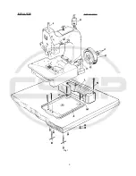
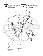
Mount the base plate (A, Fig. 1) with four screws, nuts
and washers (B) in the provided holes on the table board.
3.
Place the sewing machine on the base plate so that the
roll pin (C) in the base plate engages with the right rear
hole in the machine base.
4.
Fasten the sewing machine with the two T-screws (D) on
the base plate.
5.
Place the V-belt, supplied with the sewing table, on the
handwheel pulley .
6.
Assemble the handwheel pulley (E) with three
countersunk screws (F) to the sewing machine. Pin (G)
must engage with the hole in hub (H).
7.
Screw in needle bar guard (J).
8.
Screw in sight feed oiler (K).
9.
Align the handwheel belt guard (L) with the V-belt slot
(M) in the table board and with the handwheel pulley and
fasten it with two wood screws (N) on the table board.
10.
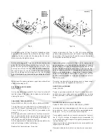
Dismount motor belt guard. Place the V-belt around the
motor pulley and slue the motor to tense the belt. The
tension on the V-belt is correct, when with moderate
finger pressure it will deflect approx. 10 mm (3/8 in.)
midway between handwheel pulley on the sewing
machine and motor pulley (see Fig. 2).
Remount motor belt guard.
INSTALACION
(Continuación)
1.
Desempaque la máquina y los accesorios.
2.
Monte la placa de base (A, Fig. 1) con los 4 tornillos,
tuercas y arandelas (B) en los huecos previstos en la
tabla de la mesa.
3.
Coloque la maquina sobre la base, de manera que el
pasador de regulación (C) en la placa base, encaje en
el hueco derecho trasero de la base de la máquina.
4.
Asegure la máquina de coser con los 2 tornillos T (D)
en la placa de base.
5.
Coloque la correa en forma de V, en la rueda del vo-
lante.
6.
Monte el volante (E) con los 3 tornillos remache (F) a
la máquina de coser. El pasador (G) debe encajar en
el hueco de la parte central del volante (H).
7.
Atornille el protector de la barra de aguja (J).
8.
Asegure la aceitera (K).
9.
Alinie el guarda correa del volante (L) con la perfora-
ción para la correa en la mesa (M) y con la rueda del
volante y sujetelo con los 2 tornillos para madera (N)
a la mesa.
10.
Desmonte el guarda correa del motor. Coloque la co-
rrea en V alrededor del volante y ajuste el motor para
tensar la correa. La tensión de la correa en V será la
correcta cuando ejerciendo presión moderada con el
dedo ceda en aprox. 10mm (3/8 pulgada) en la mitad
entre la rueda del volante en la maquina de coser y la
rueda del motor (Ver Fig. 2).
Coloque nuevamente el guarda correa del motor.
Summary of Contents for 81500A
Page 8: ...8 INSTALLATION INSTALACION ...
Page 10: ...10 ...
Page 21: ...21 ...
Page 23: ...23 Fig 10 Fig 11 Fig 11 A Fig 11 B Fig 11 C Fig 12 ...
Page 25: ...25 ...
Page 28: ...28 ...
Page 33: ...33 VIEWS AND DESCRIPTION OF PARTS VISTAS Y DESCRIPCIONES DE LAS PARTES Y PIEZAS ...
Page 34: ...34 ...
Page 36: ...36 ...
Page 38: ...38 ...
Page 40: ...40 ...
Page 42: ...42 ...
Page 44: ...44 ...
Page 46: ...46 ...
Page 48: ...48 ...
Page 50: ...50 ...
Page 52: ...52 ...
Page 54: ...54 ...
Page 56: ...56 ...
Page 58: ...58 ...
Page 60: ...60 ...
Page 62: ...62 ...
Page 64: ...64 ...
Page 68: ......


