background image

OPERATING INSTRUCTIONS

VARIABLE SHADE CONTROL

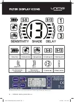
•  If the Shade is in the range of 

5-9

, press 

WELD/GRIND

 button (13) repeatedly until both 

Icon 2

 and 

Icon 4

 appears on the screen. Then press 

SHADE

 button (16) repeatedly until the desired Shade 

shown in 

Icon 8

.

•  If the Shade is in the range of 

9-13

, press 

WELD/GRIND

 button (13) repeatedly until both 

Icon 2

 and 

Icon 5

 appears on the screen. Then press 

SHADE

 button (16) repeatedly until the desired Shade 

shown in 

Icon 8

.

Note:

•  Choose an optimum Shade number for the required welding process or application.

•  If this lens does not darken when striking arc, stop welding immediately and check the helmet 

is in Weld Mode and not Grind Mode. If the issue persists, contact your local UNIMIG Service 
Department.

SENSITIVITY CONTROL

The responsiveness to different light levels in various welding processes can be adjusted in the 
range 1-5(from low to high).

Press the 

SENSITIVITY

 button (15) twice to start the setting, 

Icon 6

 will flash on the screen (from 1 to 

5). Repeatedly press the 

SENSITIVITY

 button until the desired level shown in 

Icon 6

.

• 

Turn to 1 (low)

: The photosensitivity changes to be lower. 


– Suitable for high amperage welding and welding in bright light conditions (lamp light or sunlight).

• 

Turn to 5 (high)

: The photosensitivity changes to be higher.


– Suitable for low amperage welding and using in poor light conditions.


– Suitable for use with steady arc process such as TIG welding.


– Under normal use, a higher sensitivity setting is recommended.

DELAY CONTROL

The length of time delay for the ADF to return to the light state after welding can be adjusted in the 
range 1-5 (for 0.1-0.9s). The time delay is for protection of the welder’s eyes from strong residual rays 
after welding.

Press the 

DELAY

 button (14) twice to start the setting, 

Icon 7

 will flash on the screen (from 1 to 5). 

Repeatedly press the 

DELAY

 button until the desired length of time delay shown in 

Icon 7

.

RWX6000 Welding Helmet Manual | 

7

0356 RWX6000 Helmet Manual MAY19.indd   7

8/05/2019   3:53:53 PM

Summary of Contents for RWX 6000

Page 1: ...UMCWH 2 YEAR WARRANTY 0356 RWX6000 Helmet Manual MAY19 indd 1 8 05 2019 3 53 51 PM...

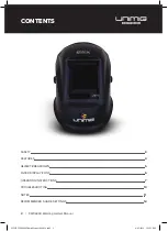
Page 2: ...MET BREAKDOWN 5 FILTER DISPLAY ICONS 6 OPERATING INSTRUCTIONS 7 TROUBLESHOOTING 10 NOTES 11 RECOMMENDED SHADE SETTINGS 12 CONTENTS 2 RWX6000 Welding Helmet Manual 0356 RWX6000 Helmet Manual MAY19 indd...

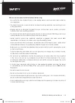
Page 3: ...ean and that no dirt is covering the sensors on the front of the lens Inspect all operating parts before each use for signs of wear or damage Any scratched cracked or pitted parts should be replaced i...

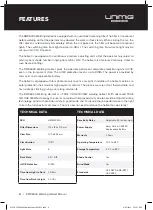
Page 4: ...tion the helmet contains an outer protection shell made of high polymer materials The plate is wear resistant thermostable and has no dregs sticking giving a very long service life The RWX6000 Welding...

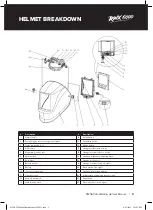
Page 5: ...ton Description 14 Delay button 15 Sensitivity button 16 Shade button 17 Headgear slider with 3 slots 18 Headgear screw Short on left 19 Headband tightness adjusting knob 20 Headgear connector 21 Head...

Page 6: ...w to 5 high 7 Delay indication 1 short 0 1s to 5 long 0 9s 8 Shade reading 9 Memory selection FILTER DISPLAY ICONS Note Buttons on the left of the screen need to be pressed twice to start any settings...

Page 7: ...SENSITIVITY button 15 twice to start the setting Icon 6 will flash on the screen from 1 to 5 Repeatedly press the SENSITIVITY button until the desired level shown in Icon 6 Turn to 1 low The photosens...

Page 8: ...e next time when you start to weld the last settings will be automatically re activated If you want to store a complete welding setting press and hold one of the memory buttons and release when the Ic...

Page 9: ...et shell must be replaced To operate more efficiently and safely please select the correct dark shade number The arc light must be visible completely by the sensor If not the filter will be transparen...

Page 10: ...DF switches during the welding Increase the sensitivity if possible Make sure the sensors are facing the arc and there are no obstructions Increase Delay 0 1 0 3 seconds may also reduce switching Inco...

Page 11: ...NOTES RWX6000 Welding Helmet Manual 11 0356 RWX6000 Helmet Manual MAY19 indd 11 8 05 2019 3 53 53 PM...

Page 12: ...eet Metal Shade 10 Shade 11 Shade 12 Shade 13 Shade 14 15 TIG Shade 9 Shade 10 Shade 11 Shade 12 Shade 13 Shade 14 MAG Shade 10 Shade 11 Shade 12 Shade 13 Shade 14 Shade 15 Arc Gouging Shade 10 Shade...

Reviews: