


Precautions Introduction
Front Panel Rear Panel Operation and Performance
AMPLIFIER
TD
-
14000
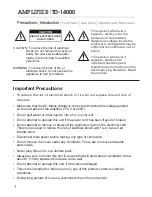
CAUTION
RISK OF ELECTRIC SHOCK
DO NOT OPEN
CAUTION: To reduce the risk of electrical
shock, do not remove the cover (or
back). No user serviceable parts
inside; refer servicing to qualified
personnel.
WARNING: To reduce the risk of fire or
electrical shock, do not expose this
appliance to rain or moisture.
This symbol, wherever it
appears, alerts you to the
presence of uninsulated
dangerous voltage inside the
enclosure - voltage that may be
sufficient to constitute a risk of
shock.
This symbol, wherever it
appears, alerts you to
important operating and
maintenance instructions in the
accompanying literature. Read
the manual.
!
!
Important Precautions
To reduce the risk of electrical shock or f ire, do not expose this unit rain or
moisture.
Make sure that the AC Mains voltage is correct and matches the voltage painted
on the rear panel of the amplifier (110 V or 220V)
Do not spill water or other liquids into or on to your unit.
Do not attempt to operate this unit if the power cord has been frayed or broken.
Do not attempt to remove or break off the ground prong from the electrical cord.
This prong is used to reduce the risk of electrical shock and f re in case of an
internal short.
Disconnect main power before making any type of connection.
Do not remove the cover under any conditions. There are no user serviceable
parts inside.
Never plug this unit in to a dimmer pack.
Always be sure to mount this unit in an area that will allow proper ventilation. Allow
about 6” (15cm) between this device and a wall.
Do not attempt to operate this unit, if it becomes damaged.
This unit is intended for indoor use only, use of this product outdoors voids all
warranties.
During long periods of non-use, disconnect the unit’s main power.
1
Summary of Contents for TD-14000
Page 17: ...16 NOTE...


