background image

UNiKA

 S-4000/S-5000/S-6000

page 2

IMPORTANT PRECAUTIONS

To reduce the risk of electrical shock or fire, do not expose this unit rain or 
moisture.

Do not spill water or other liquids  into or on to your unit.

Do not attempt to operate this unit if the power cord has been frayed or 
broken.

Do not attempt to remove or break off the ground prong from the electrical 
cord. This prong is used to reduce the risk of electrical shock and f re in 
case of an internal short.

Disconnect main power before making any type of connection.

Do not remove the cover under any conditions. There are no user 
serviceable parts inside.

Never plug this unit in to a dimmer pack.

Always be sure to mount this unit in an area that will allow proper 
ventilation. Allow about 6” (15cm) between this device and a wall.

Do not attempt to operate this unit, if it becomes damaged.

This unit is intended for indoor use only, use of this product outdoors voids 
all warranties.

During long periods of non-use, disconnect the unit’s main power.

Always mount this unit in a safe and stable manner.

Power cords should be routed so they are not likely to be walked on, 
pinched by items placed upon or against them.

Cleaning -The outside of the unit should be wipe down with a soft cloth and 
mild cleaner when needed.

Heat -The amplifier should be situated away from heat sources such as 
radiators, heat registers, stoves, or other appliances (including amplifiers) 
that produce heat.

The fixture should  be serviced by qualified service personnel when:

A. The power-supply cord or the plug has been damaged.

B. Objects have fallen, or liquid has been spilled into the unit.

C. The appliance has been exposed to rain or water.

D. The fixture does not appear to operate normally or exhibits a 

marked change in performance.

Congratulations and thank you for purchasing S-4000/S-5000/S-6000


amplifier. These amplifiers are representation of UNiKA’s continuing 

commitment to produce the best and highest quality audio products at an 

affordable price. These amplifiers are designed to provide a big impact in 

sound reproduction. Please read and understand this manual completely 

before attempting to operate your new amplifier. This booklet contains 

important information concerning the proper and safe operation of your new 

amplifier.

UNPACKING:

 Every S-4000/S-5000/S-6000 amplifier has been 

thoroughly tested and has been shipped in perfect operating condition. 

Carefully check the shipping carton for damage that may have occurred 

during shipping. If the carton appears to be damaged, carefully inspect your 

unit for any damage and be sure all accessories necessary to operate the 

system have arrived intact. In the event damage has been found or parts are 

missing, please contact your dealer for further instructions.
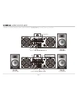
INSTALLATION:

 These amplifiers are designed to mount into a 

standard 19”rack. The front panel provides four holes used to screw the unit 

into a rack. The unit also provides a way to rear mount the unit into a rack for 

added security. Rear mounting the unit is especially recommended if the 

unit is to mounted into a mobile rack. 

INTRODUCTION

Introduction

      Front Panel      Rear Panel      Set Up      Speakon Assembly      Operating Modes      Protection      Features      Specifications

Summary of Contents for S-4000

Page 1: ...res 14 Specifications UNiKA POWER ON OFF LIMITER ON PROFESSIONAL POWER AMPLIFIER LIMITER ON PARALLEL STEREO BRIDGE 20dB SIGNAL 10dB 5dB CLIP PROTECT 0 10 0 10 CH A CH B POWER ON OFF LIMITER ON PROFESSIONAL POWER AMPLIFIER LIMITER ON PARALLEL STEREO BRIDGE 20dB SIGNAL 10dB 5dB CLIP PROTECT 0 10 0 10 CH A CH B POWER ON OFF LIMITER ON PROFESSIONAL POWER AMPLIFIER LIMITER ON PARALLEL STEREO BRIDGE 20d...

Page 2: ... lisez les avertissements supplémentaries situés dans le guide Ce symbole est utilisé pour indiquer à l utilisateur qu il trouvera d importantes instructions importantes sur l utilisation et l entretien de l appareil dans la littérature accompagnant le produit Dieses Symobl soll den Anwender vor unisollierten gefährlichen Spannungen innerhalb des Gehäuses warnen die von Ausreichender Stärke sind u...

Page 3: ...The power supply cord or the plug has been damaged B Objects have fallen or liquid has been spilled into the unit C The appliance has been exposed to rain or water D The fixture does not appear to operate normally or exhibits a marked change in performance Congratulations and thank you for purchasing S 4000 S 5000 S 6000 amplifier These amplifiers are representation of UNiKA s continuing commitmen...

Page 4: ...d Filter S Series amplifiers are cooled by two rear mounted fans Cool air from front grills is filtered and flows over the heatsinks and exhausts to back side Make sure these outlets remain clear to allow unrestricted air flow 3 AC Power Switch S Series amplifiers have a front panel AC mains power switch 4 Channel 1 Gain Control This rotary knob is used to control the output signal of channel one ...

Page 5: ... These connectors accept input signals on balanced TRS and XLR input plugs Connectors for each channel are in parallel the unused connectors may be used for loop through connection to other amplifiers XLR pin setting Pin 3 signal Negative Pin 2 signal Positive Pin 1 Ground TRS pin setting Tip signal Positive Ring signal Negative Sleeve Ground 26 Reset Button This button is designed to protect the ...

Page 6: ...r other device For example Connect a XLR cable to the input of channel one You may now connect a XLR cable from the channel one Input Thru jack to the input jack of another amplifier s channel one input This will reduce the use of Y cables OUTPUTS BINDING POST BANANA PLUG Connect your speakers to the binding post outputs on the rear of the amplifier The speaker wire may be connected by bare wire d...

Page 7: ...BRIDGE CONNECTIONS Mono bridge operation connections will follow the above descriptions however when operating in mono bridge operation the speaker connections will run between the two positive red leads Use channel two positive output terminal for the negative connection and the channel one positive output terminal for the positive connection Typical speaker output using bare wire Insert bare wir...

Page 8: ...ector insert B into the connector housing A making sure that the large notch on the outer edge of the insert lines up with the large groove on the inside of the connector housing The insert should slide easily through the housing and out the other side until it extends approximately 3 4 inch from the end of the housing 6 Slide the cable tensioner D along the cable and insert into the housing A mak...

Page 9: ...ies the two channel line inputs together so that they will both be driven by the same signal without the need for external jumpers or wiring Both amplifier channels will operate independently Though they carry the same signal their gain controls affect only their respective channels and they both must use their respected speaker outputs Never attempt to parallel the speaker outputs this may cause ...

Page 10: ...g Modes BRIDGE MONO _ _ CH 1 CH 2 _ PINOUT 1 1 POS NEG CH 2 PINOUT 2 2 POS NEG CH 2 1 2 POS NEG BRIDGE 1 1 POS NEG CH 1 H 2 C K C O L H 1 C K C O L PARALLEL STEREO BRIDGE THRU PUSH TO RESET FREQUENCY 20 Hz 20 Hz 200 Hz 200 Hz FREQUENCY CH 2 CH 1 120VAC 60Hz THRU INPUT GAIN INPUT NORMAL SUB 0 775V 1V 1 44V NORMAL SUB INPUT BRIDGE MONO _ _ CH 1 CH 2 _ PINOUT 1 1 POS NEG CH 2 PINOUT 2 2 POS NEG CH 2 ...

Page 11: ...s frequency output level Frequencies may be adjusted from 20Hz to 200Hz Page 11 Figure 18 details a typical Stereo Subwoofer set up PARALLEL SUBWOOFER This operation is similar to the Stereo Subwoofer operation but in parallel When running subwoofers it is usually recommended to run them in mono mode to achieve a cleaner tighter low end This operation allows you to run several subwoofers down to a...

Page 12: ...2 POS NEG BRIDGE 1 1 POS NEG CH 1 H 2 C K C O L H 1 C K C O L PARALLEL STEREO BRIDGE THRU PUSH TO RESET FREQUENCY 20 Hz 20 Hz 200 Hz 200 Hz FREQUENCY CH 2 CH 1 120VAC 60Hz THRU INPUT GAIN INPUT NORMAL SUB 0 775V 1V 1 44V NORMAL SUB INPUT BRIDGE MONO _ _ CH 1 CH 2 _ PINOUT 1 1 POS NEG CH 2 PINOUT 2 2 POS NEG CH 2 1 2 POS NEG BRIDGE 1 1 POS NEG CH 1 H 2 C K C O L H 1 C K C O L PARALLEL STEREO BRIDGE...

Page 13: ...el Clipping should be kept to a reasonable minimum An amplifier s peak current draw at full output power into 2 ohms is several times what the normal draw is but its various protection circuits will prevent this condition lasting more than a minute or two SHORT CIRCUIT PROTECTION The S Series amplifier comes with built in Output Short Circuit Protects The Output Short Circuit Protection protects t...

Page 14: ...mplifiers are designed with SMPS power with CLASS H S 5000 S 6000 and CLASS AB S 4000 of Power Stage Topology instead of the traditional toroidal transformer therefore the total weight of the amplifier is ultra light and also the complete performance is better THRU THRU will allow the user to daisy chain one amplifier s signal input into another amplifier Plug the signal source outputs into the fi...

Page 15: ...r 8 ohms 1dB Total Harmonic Distortion 20Hz 20KHz rated output power 8 ohms 0 02 Crosstalk 1KHz 70dB Damping Factor 400 Signal To Noise Ratio below rated output power 20Hz to 20KHz A Weighted 80 dB Power Consumption rated output power 8 ohms 12 54A 110V 17 45A 110V 24 36A 110V Output Circuitry CLASS AB CLASS H CLASS H Cooling System Dual 2 Speed Fan and Heatsinks Dimensions Height x Width x Depth ...

Page 16: ...Professional Power Amplifiers UNiKA ...

Reviews: