background image

PART I: SPE

CIFICA

TIONS

7

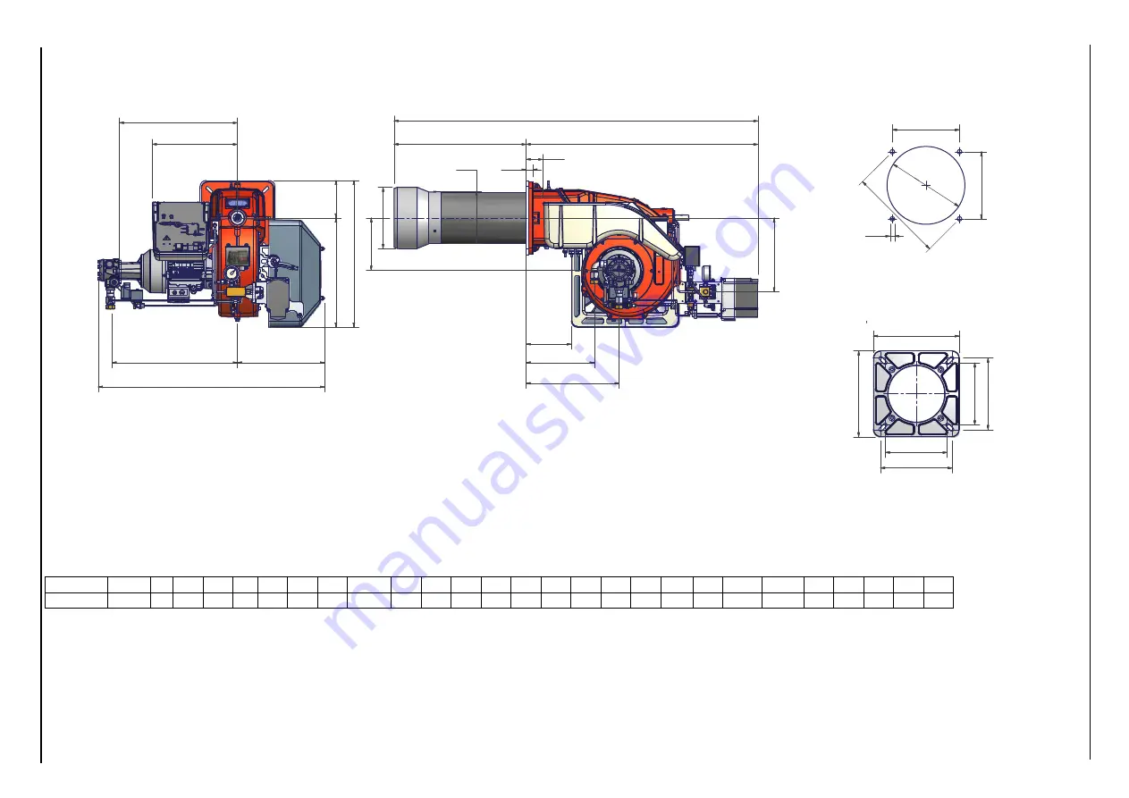
Overall dimensions (mm)     

Progressive/Fully modulating version

A

AA AB AC AD AE AH AM

B

BB

C

CC

D

F

G

H

K

L

M

N

Omin Omax

P

T

W

Y

Z

RG75 

1508

69 282 217 28 527 385 307

547

489 960 352 938 361 254 270 300 453 M10 330

216

250

233 187 608 221 155

CC

Z

AE

D

F

W

G

B

Y

AD

AA

C

A

AB

A

C

L

T

A

M

AH

BB

M

H

P

P

N

K

K

O min

O max

O

 m

in

O

 m

a

x

Burner flange

Boiler recommended drilling tem-

Summary of Contents for RG75

Page 1: ...M039338CA Rel 0 3 10 2020 BURNERS BRUCIATORI BRULERS BRENNER QUEMADORES Light oil burners MANUAL OF INSTALLATION USE MAINTENANCE RG75...

Page 2: ...y 2 SPECIAL INSTRUCTIONS FOR BURNERS z The burner should be installed in a suitable room with ventilation openings complying with the requirements of the regulations in force and sufficient for good c...

Page 3: ...irectives 2009 142 EC Gas Directive 2014 35 UE Low Tension Directive 2014 30 UE Electromagnetic compatibility Directive 2006 42 EC Machinery Directive Harmonized standards UNI EN 676 Automatic forced...

Page 4: ...ype Characteristics and test methods Industrial burners European directives 2009 142 EC Gas Directive 2014 35 UE Low Tension Directive 2014 30 UE Electromagnetic compatibility Directive 2006 42 EC Mac...

Page 5: ...les This process is achieved making pressurised oil passing through the nozzle The pump main function is to transfer oil from the tank to the nozzle in the desired quantity and pressure To adjust this...

Page 6: ...ght oil 3 OPERATION Available versions PR Progressive MD Fully modulating AB Double stage 4 BLAST TUBE S Standard 5 DESTINATION COUNTRY see data plate 6 BURNER VERSION A Standard Y SpecialeSpecial BUR...

Page 7: ...E AH AM B BB C CC D F G H K L M N Omin Omax P T W Y Z RG75 1508 69 282 217 28 527 385 307 547 489 960 352 938 361 254 270 300 453 M10 330 216 250 233 187 608 221 155 CC Z AE D F W G B Y AD AA C A AB A...

Page 8: ...D F G H K L M N Omin Omax P T W Y Z RG75 1380 69 314 217 28 527 385 547 489 833 352 938 361 254 270 300 453 M10 330 216 250 233 187 608 221 155 AE F D CC Z L W BB G AC B Y AA AD C A T AB AH M H P P N...

Page 9: ...on certain types of burner 7 11 POS OIL TRAIN 1 Filter 2 Flexible hose 3 Pump and pressure governor 6 Solenoid valve 7 Flexible hose 6 1 Solenoid valve 10 Oil distributor 11 Flexible hose 12 Pressure...

Page 10: ...t oil outlet combustion air BY BURNER CONSTRUCTOR BY OTHERS POS OIL TRAIN 1 Filter 2 Flexible hose 3 Pump and pressure governor 6 Solenoid valve 6 1 Solenoid valve 6 2 Solenoid valve 18 Flexible hose...

Page 11: ...tmospheric pressure at 1013mbar ambient temperature at 15 C NOTE The performance curve is a diagram that represents the burner performance in the type approval phase or in the laboratory tests but doe...

Page 12: ...ing are placed in each packing case z burner with gas train z ceramic fibre plait to be inserted between the burner and the boiler z envelope containing this manual To get rid of the burner s packing...

Page 13: ...4 stud bolts 5 place the ceramic fibre plait on the burner flange 6 install the burner into the boiler 7 fix the burner to the stud bolts by means of the fixing nuts according to the next picture 8 Af...

Page 14: ...nght follow the instructions of the boiler manufacturer In absence of these consider the following z Cast iron boilers three pass flue boilers with the first pass in the rear part the blast tube must...

Page 15: ...OTE in plants where gravity or ring feed systems are provided install an automatic interception device Fig 5 Gravity circuit Fig 6 Ring circuit Fig 7 Suction circuit Key 1 Manual valve 2 Light oil fil...

Page 16: ...to avoid air and fuel passing through the pump Burners come out from the factory provided for double pipe systems They can be suited for single pipe system recommended in the case of gravity feed as...

Page 17: ...ferred Junction threads elbow joints and couplings should be sealed with removable sg component The number of jun ctions should be kept to a minimum as they are a possible source of leakage z Do not u...

Page 18: ...ording to the pump provided 1 remove the closing nuts A and R on the inlet and return connections of the pump 2 screw the rotating nut of the two flexible hoses on the pump being careful to avoid exch...

Page 19: ...ssary to modify the electrical connections into the terminal box of the electric motor and replace the overload tripped relay WARNING Respect the basic safety rules make sure of the connection to the...

Page 20: ...ER OPEN OR DISMANTLE ANY COMPONENT OF THE MACHINE EXCEPT FOR ITS MAINTENANCE TO SECURE THE MACHINE ACT ON THE ISOLATOR SWITCH IN CASE OF ANOMALIES THAT REQUIRED A SHUT DOWN OF THE BURNER IT S POSSIBLE...

Page 21: ...e and at the end of this time is de energised light B4 off 7 After the ignition the servocontrol moves to the high flame position for some seconds then the operation begins and the burner switches to...

Page 22: ...ED B4 Ignition transformer operation LED B5 Fan motor overload tripped LED S1 Main switch S2 Reset pushbutton for control box O1 EVG1 solenoid valve operation LED O2 EVG2 solenoid valve operation LED...

Page 23: ...ring commissioning operations do not let the burner operate with insufficient air flow danger of formation of carbon monoxide if this should happen make the fuel decrease slowly until the normal combu...

Page 24: ...5 10 5 10 8 11 1 11 4 12 1 13 8 15 3 16 5 18 4 20 0 22 4 36 2 36 7 15 5 7 0 8 7 9 4 10 0 11 4 13 2 14 9 17 2 19 6 23 1 25 1 33 2 33 7 15 2 7 5 11 3 11 8 10 3 13 0 14 3 15 3 17 2 19 2 21 8 24 2 30 4 3...

Page 25: ...t the return pressure at 11bar supply at 20bar on the delivery to get a 220kg h flow rate If the return pressure needed is 5bar instead act on the V adjusting screw on the pressure governor see chapte...

Page 26: ...PART III OPERATION 26 FLUIDICS KW3 60 NOZZLE SUPPLY PRESSURE 20 bar VISCOSITY AT NOZZLE 5 cSt Pressure on return bar Flow rate kh h The nominal size of the nozzle is indicated at the ends of the curve...

Page 27: ...27 FLUIDICS KW3 60 NOZZLE SUPPLY PRESSURE 20 bar VISCOSITY AT NOZZLE 5 cSt Pressure on return bar Flow rate kh h Pressure on return bar Flow rate kh h The nominal size of the nozzle is indicated at th...

Page 28: ...r is not provided with the manual control of the air damper The adjustment of the cams is carried out by means of a screwdriver by twisting the VS screw located inside the cam z Berger STA6 this actua...

Page 29: ...for a while then replace it the actuator will shift just few degrees towards the low flame position and then will move to the new high flame position 19 Once the adjustmet is performed check again th...

Page 30: ...ted at the maximum output go on with the point to point adjustment on the SV2 adjusting cam as to reach the minimum output point as described on the next steps 12 as for the point to point regulation...

Page 31: ...ine checks that the pressure does not exceed a default value This value must not be higher than the maximum acceptable pressure on the return line this value is reported on the specification table A p...

Page 32: ...te the bur ner at a lower power progressively shift back the combustion head towards the MIN position screwing the screw VRT The ID index shows how much the combustion head moved Attention if it is ne...

Page 33: ...st and replace if necessary z remove and clean the oil nozzles IMPORTANT do not clean the nozzles using metallic or sharp utensils use only solvents or steam at the end of maintenance operations refit...

Page 34: ...Note to replace the combustion head reverse the procedure described above Note the figures below are indicative only Electrodes Adjustment Important Note Check the ignition and detection electrodes af...

Page 35: ...y replace the bulb 6 replace the photocell into its slot Checking the detection current To check the detection signal follow the scheme in the picture below If the signal is less than the value indica...

Page 36: ...PART IV MAINTENANCE 36 WIRING DIAGRAMS Refer to the attached wiring diagrams WARNING 1 Electrical supply 230V 400V 50Hz 3N a c 2 Do not reverse phase with neutral 3 Ensure burner is properly earthed...

Page 37: ...vating the diagnostic functions The multicolour LED is the key indicating element for both visual diagnosis and interface diagnosis s Red l Yellow o Green Key m Off l Yellow o Green s Red Diagnosis of...

Page 38: ...tat or pressurestat SB Safety limit thermostat Si External primary fuse W Limit thermostat or pressure switch Z Ignition transformer t4 Interval from flame signal to release BV2 TSA Ignition safety ti...

Page 39: ...laid separately 20m LMO14 LMO24 LMO44 Terminal 1 5 A 5 A 5 A Terminals 3 and 8 3 A 5 A 5 A Terminals 4 5 and 10 1 A 1 A 1A Terminals 6 1 A 1 A 2A Flame supervision with QRB and QRC QRB QRC Min detect...

Page 40: ...ia L Galvani 9 35011 Campodarsego PD ITALY Tel 39 049 9200944 Fax 39 049 9200945 9201269 web site www cibunigas it e mail cibunigas cibunigas it Note specifications and data subject to change Errors a...

Reviews: