


C.I.B. UNIGAS - M039119CE
7
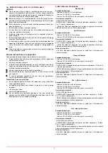
BURNERS SPECIFICATIONS
Burner model identification
Burners are identified by burner type and model. Burner model identification is described as follows.
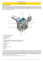
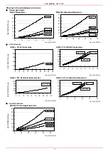
Matching the burner to the boiler
The burners described in this manual have been tested with combustion chambers that comply with EN676 regulation and whose
dimensions are described in the diagram . In case the burner must be coupled with boilers with a combustion chamber smaller in dia-
meter or shorter than those described in the diagram, please contact the supplier, to verify that a correct matching is possible, with res-
pect of the application involved. To correctly match the burner to the boiler verify the necessary input and the pressure in combustion
chamber are included in the burner performance curve; otherwise the choice of the burner must be revised consulting the burner manu-
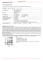
facturer. To choose the blast tube lenght follow the instructions of the boiler manufacturer. In absence of these consider the following:
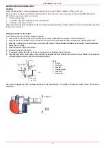
z
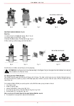
Cast-iron boilers, three pass flue boilers (with the first pass in the rear part): the blast tube must protrude no more than 100 mm into
the combustion chamber.
z
Pressurised boilers with flame reversal: in this case the blast tube must penetrate at least 50 - 100 mm into combustion chamber in
respect to the tube bundle plate.
The length of the blast tubes does not always allow this requirement to be met, and thus it may be necessary to use a suitably-sized
spacer to move the burner backwards or to design a blast tube tha suites the utilisation (please, contact the manifacturer).
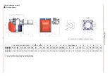
Type
NG550
Model
M-. PR. S. .* A. 0. 50
(1) (2) (3) (4) (5) (6) (7) (8)
(1) BURNER TYPE
NG - Natural gas burner
LG - L.P.G. burner
NGX - Low NOx burners
(2) FUEL
M - Natural gas
L - LPG
(3) OPERATION
TN - Single stage
AB - Double stage
PR - Progressive MD - Fully modulating
(4) BLAST TUBE
S - standard L - extended
(5) DESTINATION COUNTRY
see data plate
(6) BURNER VERSION
A - Standard
(7) EQUIPMENT
0 = 2 gas valves
1= 2 Gas gas proving system (option)
7 = 2 gas maximum gas pressure switch
8= 2 Gas gas proving system (option) + maximum gas pressure switch
(8) GAS CONNECTION
25 = Rp1 32 = Rp1”
1/4
40 = Rp1”
1/2
50 = Rp2
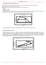
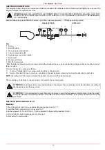
Fig. 4
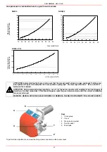
Key
a) Heat output in kW
b) Lenght of the flame tube in meters
c) Flame tube firing intensity in MW/m
3
d) Combustion chamber diameter (m)
Fig. 4 - Firing intensity, diameter and lenght of the test flame tube as a function of the heat
input in kW.


