


C.I.B. UNIGAS - M039119CE
33
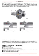
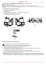
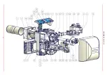
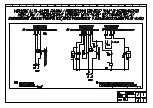
Electrodes position setting
ATTENTION:
avoid
the ignition and detection electrodes to contact metallic parts (blast tube, head, etc.), otherwise the boiler’s opera-
tion would be compromised. Check the electrodes position after any intervention on the combustion head. The gap between the ignition
electrode and the ground is
4 ÷ 5 mm
(see Fig. 46).
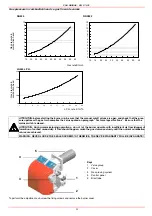
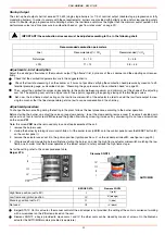
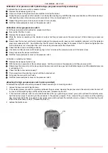
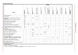
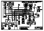
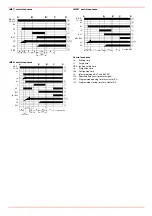
Checking the ionisation current
If the burner locks out, execute the following inpesctions. To measure the detection signals refer to the diagrams in Fig. 47 . If the signal
is less than the value shown, check the position of the detection electrode, the electrical contacts and if necessary replace the detection
electrode (see “Electrodes position setting” on page 33).
Fig. 47
Seasonal stop
To stop the burner in the seasonal stop, proceed as follows:
1
turn the burner main switch to 0 (Off position)
2
disconnect the power mains
3
close the fuel valve of the supply line
Burner disposal
In case of disposal, follow the instructions according to the laws in force in your country about the “Disposal of materials”.
Fig. 46
Detection electrode
ignition electrode
Ground electrode
detection electrode
NG550
NGX550
Connector
µA DC SCALE
2
Detection electrode
Flame
Control box
Minimum detection signal
Siemens LME21-22
3 µA