background image

SIEMENS OIL BURNERS AUTOMATIC CONTROLLER LOA24

Use

LOA... safety devices are intended for use solely with QRB... photoresi-
stors, for lighting and controlling low capacity forced air light oil burners
with max. capacity 30 kg/h in accordance with standard DIN 4787.
The One or two flamess are lit through electrical connections with or
without post-ignition.

To replace LAl... AND LAB.. WITH LOA...

LOA... models can be used as replacement for LAl... and LAB.. controllers
by means of the adapter KF8819 and without the need to change the
electrical wiring. Because the LOA is smaller in dimensions, when it is
used with the adapter the external dimensions are almost identical, which
means that there is no need to move the reset button.

Performance

The controllers just need plugging in, so they can be mounted in almost
any position: on the burner, on the electrical panel or on the control panel.
The casing is made of robust heat-resistant plastic and contains:

z

the thermic programmer operating a multiple switch control system
with ambient temperature compensator 

z

flame signal amplifier with flame relay

z

warning light indicating lockout and associated sealed reset button.

The plug-in socket, also made of robust heat-resistant plastic, contains
the 12 terminals and also:

z

3 neutral terminals, ready wired up to terminal 2

z

4 earth terminals for earthing the burner

z

2 supplementary terminals numbered “31” and “32”.

The socket has two openings at the bottom for the leads; 5 others with
threaded connection for cable holders PG11 or 3/4UNP for non-metallic
sleeves are located on a mobile stuffing box, one on either side and 3 on
the front.
There are two flexible metal tongues on the sides of the socket for moun-
ting.
To dismantle it only requires gentle pressure with a screw driver in the slot
of the mounting guide. The base dimensions of the socket are exaclty the
same as for types LAB/LAI and there is no difference in the diameter of
the reset button, the two mounting screws and the flange of the burner
earth.

Safety at low voltage levels

Safety devices against any reduction in the mains voltage operate on a
special electronic circuit which, in the event of the power supply falling
below 165V~, stops the burner switching on without releasing the fuel and
locks out the apparatus.

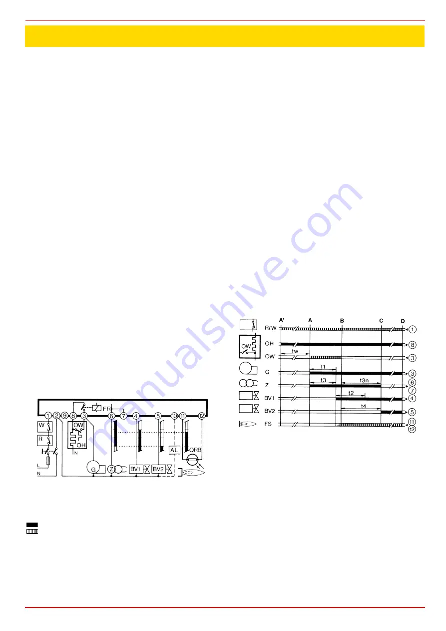
Wiring diagram of the programme

To ensure correct wiring it is essential to observe local standards and fol-
low the instructions of the burner manufacturer with regard to assembly
and start-up.

Program's legend:

Controller output signals
Required input signals

A’Burner start up with light oil pre-heater OH

A

Burner start-up without light oil pre-heater

B

Flame lit

C

Normal operation

D

Normal stop through R

tw

Oil pre-heating time until operational all clear given through 
contact OW

tl

Pre-purge time

t3

Pre-ignition time

t2

Safety time

t3n

Post-ignition time

t4

Interval between the flame lighting and energising of solenoid 
2a at terminal 5

Internal layout

AL

Optical alarm

BV.

Fuel valve

EK

Reset button

FR

Flame relay

fr

Flame relay contacts

FS

Flame alight signal

G

Burner motor

K

Flame relay anchor to delay the tzl command in the event of a 
premature flame signal or endorse it where the signal is
correct.

OH

light oil pre-heater

OW

Operational all-clear contact

QRB Photo-resistant cell (flame detector)
R

Thermostat or pressure switch

TZ

Thermo-electric programmer (bimetal system)

tz..

TZ contacts

V

Flame signal amplifier

W

Safety thermostat or pressure switch

Z

Ignition transformer

The above are safety devices!

To tamper with them in any way may have unforeseeable conse-
quences!

Do not open them!

Technical characteristics

Voltage

220V -15%..240V+10% or
100V -15%...110V+10%

Frequency

50...60Hz +/- 6%

External fuse

max.10A slow action

Contact flow:
- terminal 1

5A

- terminal 3

5A (incl.capacity absorbed by motor and 
pre-heater)

Terminal flow:
terminals 4, 5 &10

1A

terminals 6&7

2A

terminal 8

5A

Absorbed cap

3VA

Protection

IP40

Premitted temp:
operational

-20...+60°C

transport & storage

-50...+60°C

APPENDIX

Summary of Contents for IDEA Series

Page 1: ...MANUAL OF INSTALLATION USE MAINTENANCE LO280 LO400 IDEA Series Light oil Burners M039134CD Rel 3 0 03 2010 BURNERS BRUCIATORI BRULERS BRENNER QUEMADORES...

Page 2: ...ingle stage burners 15 Priming the pump 15 Choosing oil nozzles 15 Oil rate adjustment High low flame burners 16 Pumps f 21 Adjusting the combustion head 21 Adjustments for burners with hydraulic ram...

Page 3: ...ins electricity gas oil or other fuel z Observe caution with hot burner components These are usually near to the flame and the fuel pre heating system they become hot during the unit operation and wil...

Page 4: ...f toxic or explosive mixtures DIRECTIVES AND STANDARDS Gas burners European directives Directive 90 396 CEE Gas Appliances Directive 2006 95 EC on low voltage Directive 2004 108 CEE on electromagnetic...

Page 5: ...PERATION Available versions TN Single stage AB Double stage 4 BLAST TUBE S Standard L Extended 5 DESTINATION COUNTRY see data plate 6 BURNER VERSION A Standard M With hydraulic ram BURNERS LO280 G TN...

Page 6: ...length for mod LO400 see paragraph How to modify the the blast tube length Boiler recommended drilling template and burner flange A S A L B S B L C F G H K1 K2 L M N Omin Omax P T X Y LO280 733 878 16...

Page 7: ...e paragraph Adjusting the combustion head the minimum output point is rea ched setting the combustion head to its MIN position During the first ignition the combustion head is set in order to find a c...

Page 8: ...picture Fig 9 If you modify the blast tube length you have to modify also the combustion head length by reading the following instructions 1 Loosen the light oil feeding pipes connected to the nozzle...

Page 9: ...C I B UNIGAS M039134CD 9 6 Assemble again the combustion head See Removing the combustion head Part III of this user s manual Fig 10 Fig 11 Fig 12 Fig 13 Fig 14 Fig 15 10 22 VA A 10 13...

Page 10: ...r follow the procedures laid down by current laws on disposal of materials Fitting the burner to the boiler To perform the installation proceed as follows 1 place the 4 stud bolts on the hole of the b...

Page 11: ...ween terminals T6 and T8 on CN2 TAB connector external side link male connector remove this bridge before thermostat connection Fig 19 Single stage burners Fig 20 High Low flame burners Key C1 C2 Time...

Page 12: ...le pipe system as for the single pipe system a pipe that connects the tank to the pump s inlet is used besides another pipe that connects the pum s return port to the tank as well The excess of oil go...

Page 13: ...z Care must be taken when installing the pump not to force the pump shaft along its axis or laterally to avoid excessive wear on the joint noise and overloading the gears z Pipes should not contain a...

Page 14: ...ne plugs A and B 3 Screw the rotating nut D of the two flexible hoses F on the pump being careful to avoid inverting the delivery and return lines 4 Fix the flexible hoses as showed on Fig 27 Fig 27 5...

Page 15: ...sing oil nozzles Tab 1 Single stage burners Note all pumps are set to 12 bar The nozzle rate must be higher than the rate referred to the minimum burner output Key EVG Light oil solenoid valve M Manom...

Page 16: ...82 2 92 3 02 3 12 3 22 3 31 3 40 3 49 3 58 3 66 3 74 3 83 3 90 0 75 2 55 2 70 2 85 2 99 3 12 3 25 3 37 3 49 3 60 3 71 3 82 3 93 4 03 4 13 4 23 4 32 4 41 4 50 0 85 2 89 3 06 3 23 3 39 3 54 3 68 3 82 3...

Page 17: ...IV Siemens between the cams I and II Then passing from the low to high flame stage or viceversa change the setting according to the flame composition if cam III is too near to the low flame position c...

Page 18: ...operly sized nozzles and adjusting the fuel pressure at the pump inlet see the diagram Fig 30 and Fig 31 To choose the nozzles refer to Tab 3 and Tab 4 for pump pressure regulation see on pag 21 For f...

Page 19: ...it burn at low flame remove the bridge between terminals T6 and T8 z Adjust the air flow in low flame by working on the proper cam page 20 z Prime the second nozzle using the following procedure z Sta...

Page 20: ...lame could fade because of too much air mod LO280 Pumps Berger STA4 5 Siemens SQN72 BERGER STA Siemens SQN72 Air adjustment in high flame cam I I red Air adjustment in low flame Stand by Ignition cam...

Page 21: ...bustion head in the MAX position corresponding to the maximum power combustion head all forward To operate the burner at a lowest strenght progressively shift back the combustion head toward the MIN p...

Page 22: ...ame stage turn counterclockwise to decrease the air flow z At the end of settings tight again the nut 2 b High flame setting To set the high flame proceed as follow z Close the contact of the second s...

Page 23: ...AND SAFE FUNCTIONING OF THE BURNER THEREFORE ANY OPERATION OF THE APPLIANCE MUST BE PREVENTED WHICH DEPARTS FROM THE INSTALLATION OPERATIONS OR WHICH HAPPENS AFTER TOTAL OR PARTIAL TAMPERING WITH THE...

Page 24: ...that the set of thermostats or pressure switches enables burner operation z The burner starting cycle begins and the control box starts the burner fan while the ignition transformer switches on at the...

Page 25: ...t be performed using solvent not metal tools At the end of maintenance operations after first reassembling the burner light the flame and check its shape replacing the nozzle whe never a questionable...

Page 26: ...e the combustion head see Removing the combustion head on page 25 z Remove the 7 screws V5 V11 which fasten the components plate Fig 44 z Remove the rod T from its housing as shown in Fig 45 z Hook th...

Page 27: ...rner components plate z Reassemble burner components plate and tighten the 6 screws V5 V11 Fig 44 z Refit the rod T Fig 45 z Reassemble the combustion head and tighten the 4 screws V1 V4 Fig 41 Fig 44...

Page 28: ...le mod LO280 z Loose screw V that fasten the combustion head and remove the head from the nozzle holder Fig 49 Fig 50 In order to remove the nozzle it is important to use two wrenches as shown in to a...

Page 29: ...s LO400 z Unscrew the Allen screw VT and remove the combustion head TC as shown on Fig 51 Fig 52 z Unscrew the nozzles using two wrenches 16 and 24 mm as shown in Fig 53 Fig 53 Double stage burners Fi...

Page 30: ...If the signal doesn t suit the suggested value check the electric terminal the cleaning of the combustion head and the position of the photoelectric cell replace it if necessary A 8 10 mm B 4 5 6 mm...

Page 31: ...AND LOCKS BURNER STARTS AND LOCKS BURNER DOESN T SWITCH TO HIGH FLAME BURNER LOCK DURING OPERATION BURNER LOCKS AND REPEATS CYCLE DURING OPERATION MAINS SWITCH OPEN z FUSES INTERVENTION z MAXIMUM PRE...

Page 32: ...SING 2 GENERATOR GASKET 3 COVER 4 MOTOR 5 FAN WHEEL 6 STANDARD BLAST TUBE 7 PUMP 8 1 LONG IGNITION ELECTRODE 8 2 NOZZLE 8 3 COMBUSTION HEAD 8 4 NOZZLE HOLDER 8 5 FLANGE 8 7 IGNITION CABLE 9 AIR DAMPER...

Page 33: ...C I B UNIGAS M039134CD 33...

Page 34: ...TION TRANSFORMER 2170231 2170231 2170231 2170231 2170231 ELECTRIC MOTOR 2180717 2180717 2180717 2180714 2180714 EVG2 SOLENOID VALVE 2190638 2190638 HYDRAULIC RAM 2330053 2330053 FLEXIBLE HOSES 234FX22...

Page 35: ...MENS CONTROL BOX LOA24 44 SIEMENS CONTROL BOX LB INDICATOR LIGHT FOR BURNER LOCK OUT LBF BURNER IN LOW FLAME INDICATOR LIGHT LEVG1 INDICATOR LIGHT FOR OPENING OF ELECTRO VALVE EVG1 LTA IGNITION TRANSF...

Page 36: ......

Page 37: ......

Page 38: ......

Page 39: ......

Page 40: ......

Page 41: ......

Page 42: ......

Page 43: ...here is no difference in the diameter of the reset button the two mounting screws and the flange of the burner earth Safety at low voltage levels Safety devices against any reduction in the mains volt...

Page 44: ...ds about AC 175 V Time supervision oil pre heater If the oil pre heater s release contact does not close within 10 minutes the burner control will initiate lock out Controlled intermittent operation A...

Page 45: ...voltage lslslslslsl Yellow red Fault alarm sssssssssss Red Output of fault code refer to Fault code table smsmsmsmsm Red off Extraneous light prior to burner start up osososososo Green red Interface d...

Page 46: ...ishment C Operating position D Controlled shut down by R C1 Microcontroller 1 C2 Microcontroller 2 General unit data Mains voltage AC 230 V 10 15 AC 120 V 10 15 Mains frequency 50 60 Hz 6 External pri...

Page 47: ......

Page 48: ...and data subject to change Errors and omissions excepted C I B UNIGAS S p A Via L Galvani 9 35011 Campodarsego PD ITALY Tel 39 049 9200944 Fax 39 049 9200945 9201269 web site www cibunigas it e mail...

Reviews: