background image

PART III: OPERATION

38

Choose “ControllerParam” and press ENTER: the following menu is shown:

Choose “

SetPointW1

” and press ENTER:

Curr:

 it shows the current set-point; use the arrows keys to change.

NOTE:

 the availabel range for this parameter depends on the probe provided; the unit measure of the detected value and its limits are

bound up with parameters set at the “Service” level.
Once the new set-point is set, confirm by pressing ENTER, otherwise exit without changings by pressing ESC.
Press ESC to exit the set-point programming mode.
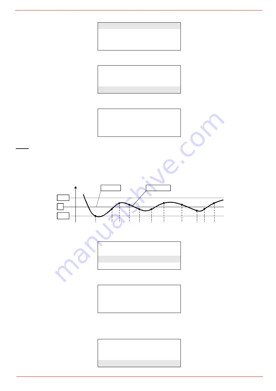
Once the temperature set-point W1 is imposed, set the Switch-on (SDon) and the Switch-off (SDoff) point of the 2-position controller:

To set these values, select the item SD_ModOn (SDOn), by scrolling down the “Load controller” menu with the arrow keys and press
ENTER:

the display will show:

The deafult value for this parameter is1% that is, the burner will light again at a temperature 1% lower than the set-point. Change value,
if needed, by means of the arrow keys; press ENTER to confirm and the press ESC to exit. Press only ESC to exit without changing.
Now choose SD_ModOff always scrolling down theLoad Controller menu, by menas of the arrow keys, and press ENTER.

ControllerParam
Configuration
Adaption
SW Version

ContrlParamList
MinActuatorStep
SW_FilterTmeCon
SetPointW1

SetpointW1
Curr:

90°

New:

90°

SetpointW1
SetpointW2
SD_ModOn
SD_ModOff

SD_ModOn
Curr::

1.0%

New:

1.0%

SetpointW1
SetpointW2
SD_ModOn
SD_ModOff


Setpoint

Actual value

SDoff

W

SDon

Summary of Contents for HR2050

Page 1: ...M039409CC 0 0 01 2023 BURNERS BRUCIATORI BRULERS BRENNER QUEMADORES MANUAL OF INSTALLATION USE MAINTENANCE LMV5x Microprocessor controlled Gas light oil burners HR2050 HR2060 HR2080...

Page 2: ...non original components whether spare parts kits accessories and optionals Force majeure Furthermore the manufacturer declines all responsibility for non compliance with this manual Personnel training...

Page 3: ...rner shut down reser the control box by means of the RESET pushbutton If a second shut down takes place call the Tech nical Service without trying to RESET further The unit shall be operated and servi...

Page 4: ...the ones stated Do not use the burner in potentially explosive environments Do not remove or by pass any machine safety devices Do not remove any protection devices or open the burner or any other com...

Page 5: ...wo pressure regulators one for the high and one for low pressure in double stage systems with one nozzle The adjustable combustion head can improve the burner performance The combustion head determine...

Page 6: ...R2080 Output min max kW 2500 15200 2500 16000 2500 19000 Fuel MG Natural gas Light oil Category see next paragraph Gas rate min max min max Stm3 h 265 1608 265 1693 265 2011 Pressure mbar see Note 2 L...

Page 7: ...6 15 595 132 768 1898 683 2431 1604 827 845 730 949 M16 948 670 239 215 827 1477 310 1314 365 HR2050 100 741 1748 866 15 595 145 768 1898 683 2447 1620 827 845 730 949 M16 948 670 239 215 874 1477 350...

Page 8: ...75 850 950 M16 1117 790 1066 239 215 827 1336 310 1375 HR2060 100 2377 741 831 868 7 645 321 920 145 885 1877 728 2329 1479 850 775 850 950 M16 1117 790 1113 239 215 874 1336 350 1375 HR2060 125 2377...

Page 9: ...00 EK 790 395 395 790 395 395 P750 1117 16 M 850 395 395 850 395 395 395 395 30 30 30 395 395 30 700 2178 1375 900 215 741 15 970 550 1892 2442 775 125 239 731 353 1196 1326 638 861 1759 425 950 742 7...

Page 10: ...PART I SPECIFICATIONS 10 Support frame for burner size 2080 968 1255 1690 1150 1028 164 1370 50 1773 1200 684...

Page 11: ...Pressure switch 16 One way valve 18 Flexible hose 19 Manual valve 20 Pressure gauge MAIN GAS TRAIN 40 Manual valve 41 Bellows unit 42 Filter 43 Pressure switch PGMIN 44 Safety valve with built in gas...

Page 12: ...p and pressure governor 4 Electrical motor 6 Solenoid valve 10 Oil distributor 12 Pressure gauge 13 Pressure governor 14 Actuator 15 Pressure switch 16 One way valve 18 Flexible hose 19 Manual valve 2...

Page 13: ...ilable gas pres sure value upstream the burner s gas valve Then subtract the backpressure The result is called pgas Draw a vertical line matching the furnace input value 600kW in the example quoted on...

Page 14: ...is diagram the maximum output point is usually reached by adjsuting the combustion head to its MAX position see paragraph Adjusting the combustion head the minimum output point is reached setting the...

Page 15: ...ESSURE mbar HR2080 Stm3 h Caution the gas rate value is quoted on the x axis the related network pressure is quoted on the y axis pressure value in the combustion chamber is not included To know the m...

Page 16: ...ssure in the combustion head insert the pressure gauge probes one into the combustion chamber s pres sure outlet to get the pressure in the combustion chamber and the other one into the butterfly valv...

Page 17: ...ssure burner head vs natural gas flow rate Curves are referred to pressure 0 mbar in the combustion chamber Gas pressure in combustion head HR2050 Stm3 h Gas pressure in combustion head HR2060 Stm3 h...

Page 18: ...2270 mm x 1720 mm x 1320 mm L x P x H HR2080 2570 mm x 1900 mm x 1750 mm L x P x H Such packages fear moisture and are not suitable for stacking Packing cases of this type are affected by humidity an...

Page 19: ...spray adhesive on the flange 5 install the burner into the boiler 6 fix the burner to the stud bolts by means of the fixing nuts according to the picture below 7 After fitting the burner to the boiler...

Page 20: ...choose the blast tube lenght follow the instructions of the boiler manufacturer In absence of these consider the following Cast iron boilers three pass flue boilers with the first pass in the rear pa...

Page 21: ...ns ATTENTION Before executing the connections to the gas pipe network be sure that the manual cutoff valves are closed PS PSH PSL PSL PSH PS M M MB DLE VGD MBE gas inlet gas inlet gas inlet Legend 1 F...

Page 22: ...ording to the procedure set by laws in force CAUTION The direction of gas flow must follow the arrow on the body of the components mounted on the gas ramp valves filters gaskets NOTE the bellows unit...

Page 23: ...riate sealing agent 2 Insert MB DLE note position of O rings 3 Remove MultiBloc between the threaded flanges 4 After installation perform leakage and functional test 5 Disassembly in reverse order osi...

Page 24: ...pressure switch 4 PGMAX maximum gas pressure switch 5 Actuator with integrated pressure stabiliser 6 On Off actuator 7 Valve body Threaded 8 Valve body Flange On equipment versions Facile VD R must b...

Page 25: ...ens VGD VRD SKPx5 Auxiliary optional micro switch Gas valve If the auxiliary microswitch POC is required a dedicated actuator different from the one usually supplied must be ordered The con nection is...

Page 26: ...the gas train in installed execute the electrical connections for all its items gas valves group gas proving system pressure switches Gas Filter if provided The gas filters remove the dust particles t...

Page 27: ...o ambient pressure Test atmospheric pressure EV2 clo ses and keep this position for a preset time test time td1 The pressure switch PGCP has not to detect a rise of pressure Test space filling EV1 ope...

Page 28: ...stallation can be considered self ble please read carefully the warnings chapter at the beginning of this manual 1 3 2 Key 1 Manual valve 2 Light oil filter 3 Light oil feeding pump 4 One way valve 5...

Page 29: ...ould not contain air pockets Rapid attachment joint should therefore be avoided and threaded or mechanical seal jun ctions preferred Junction threads elbow joints and couplings should be sealed with r...

Page 30: ...ressure 2 bar Maximum speed 3600 rpm Key 1 Inlet G3 4 2 Pressure gauge port G1 4 3 Vacuum gauge port to measure the inlet vacuum G1 4 4 To pressure adjusting valve G3 4 Key 1 Pressure regulator 2 Pres...

Page 31: ...trol box please refer to the clabeling recommendations avaible on the Siemens CD attached to the burner WARNING Respect the basic safety rules make sure of the connection to the earthing system do not...

Page 32: ...NG WITH THESE E G DISCONNECTION EVEN PARTIAL OF THE ELECTRICAL LEADS OPENING THE GENERATOR DOOR DISMANTLING OF PART OF THE BURNER NEVER OPEN OR DISMANTLE ANY COMPONENT OF THE MACHINE EXCEPT FOR ITS MA...

Page 33: ...lame operation LED B3 Lo flame operation LED B4 Ignition transformer operation LED B5 Fan motor overload tripped LED B6 Stand by signalling lamp G1 Gas valves EV2 operation signalling lamp G2 Gas valv...

Page 34: ...the actuator goes to the high flame position after some seconds the two stage operation begins the burner is driven automatically to high flame or low flame according to the plant requirements Operati...

Page 35: ...ust the gas flow rate in the high flame stage as to meet the values requested by the boiler utilisation Start up procedure 1 Turn the burner on 2 the LMV control box starts the system test cycle the A...

Page 36: ...vides the following items Normal operation by selecting this item and pressing the ENTER key the main page is showed press ESC to go back to the main menu Status Reset it shows system errors or faults...

Page 37: ...age enter the main menu by pressing the ESC key twice by means of the arrow keys select Params Display press ENTER the system will ask you to enter the proper password by means of the arrow keys selec...

Page 38: ...the 2 position controller To set these values select the item SD_ModOn SDOn by scrolling down the Load controller menu with the arrow keys and press ENTER the display will show The deafult value for...

Page 39: ...ime Winter WIN Time operation and the continent EU Europe US United States choose the Summertime Wintertime mode desired and cofirm by pressing ENTER press ESC to exit Set the time zone Time EU US in...

Page 40: ...This function is already set by the Technical service access by reserved password if this function is enabled when the burner starts upthe Thermal shock protection activated message will be showed If...

Page 41: ...tand by If the BurnerOn mode is choosen the burner does not follow the modulator and probe settings but operates at the set load For further details see the LMV5x annexed manuals SetLoad Curr 0 0 New...

Page 42: ...on reduces start flow rate anticlockwise rotation increases it Do not use a screwdriver on the screw VR The pressure stabilizer is adjusted by operating the screw VS located under the cover C By screw...

Page 43: ...Refit the transparent plastic cover on the pressure switch Calibration the maximum gas pressure switch when provided To calibrate the maximum pressure switch proceed as follows according to its mounti...

Page 44: ...justment is accomplished Adjustment procedure for light oil operation The light oil flow rate can be adjusted choosing a nozzle that suits the boiler utilisation output and setting the delivery and re...

Page 45: ...PART III OPERATION 45 Pump flow rate Nozzle flow rate...

Page 46: ...ig 5 4 As for setting the fuel air ratio curve see the LMV related manual 5 Only if necessary adjust the supply pressure as follows insert a pressure gauge into the port shown on figure and act on on...

Page 47: ...hole range of the burner output In case of inacceptable values reduce from 20 to 15 the overpressure later on repeat the adjustments described above Pressure governor on return line Pressure governor...

Page 48: ...e detection electrode photoelement according to the burner models replace it if necessary in case of doubt check the detection circuit after the burner start up Clean and grease leverages and rotating...

Page 49: ...ed to the last check You can change the filter without removing the fitting 1 Interrupt the gas supply closing the on off valve 2 Remove screws 1 4 using the Allen key n 3 and remove filter cover 5 in...

Page 50: ...to push 1 2 3 4 5 6 7 1 Position VD on VB fig 2 3 2 Slide VD forward up to the stop fig 4 3 Screw VD on with 2 M5 screws for each max 5 Nm 44 in lb fig 5 6 4 VD can be mounted rotated by 180 fig 7 VB...

Page 51: ...give the power to any electrical equipmente on the filter Removing the combustion head 1 Remove the top H 2 Remove the UV detector out of its housing disconnect electrode cables and the light oil fle...

Page 52: ...metallic parts blast tube head etc otherwise the boi ler s operation would be compromised Check the electrodes position after any intervention on the combustion head A B C 696 583 169 747 550 12 75 74...

Page 53: ...ectrodes position after any intervention on the combustion head ATTENTION avoid the electrode to get in touch with metallic parts blast tube head etc otherwise the boiler operation would be compromise...

Page 54: ...necessary to carry out a technical diagnosis and if necessary an overall repair The burner status is considered to be at its limit if it is technically impossible to continue using it due to non compl...

Page 55: ...Check air pressure switch functions and links Burner control damaged Replace burner control BURNER LOCKS OUT WITHOUT ANY GAS FLOW Gas valves don t open Check voltage on valves if necessary replace val...

Page 56: ...ition transformer or into the electrodes Improve the installation Ignition transformer damaged Replace the transformer PUMP TOO NOISY Suction too high over 0 35 bar dirty filters check valve in the ta...

Page 57: ......

Page 58: ......

Page 59: ......

Page 60: ...a L Galvani 9 35011 Campodarsego PD ITALY Tel 39 049 9200944 Fax 39 049 9200945 9201269 web site www cibunigas it e mail cibunigas cibunigas it Note specifications and data subject to change Errors an...

Page 61: ...d an earth external wire for the motor ground The cable for the 4 20mA signal that controls the VSD must be shielded only LMV5x side ends connected to the equipotential terminal If the VSD is not insi...

Page 62: ...Annex1 Example for motor cable...

Page 63: ......

Page 64: ...Annex 2 Example for sensor cable...

Page 65: ......

Page 66: ......

Page 67: ...E Power supply Line voltage Gas L1 High Voltage Transformer N M Power supply Line voltage FE X73 Speed sensor VSD Fan Motor Separate conduit shielded line voltage cable X70 X10 02 X9 01 X4 02 Separate...

Page 68: ...ion and current fuel throughput The LMV52 system uses an O2 sensor QGO20 an external O2 module and the standard components of the LMV51 sys tem The PLL O2 module is a detached measuring module for the...

Page 69: ...defined system cables AGG5 641 and AGG5 631 result from the points of intersection in the graph 50 48 46 44 42 40 38 36 34 32 30 28 26 24 22 20 18 16 14 12 10 8 6 4 2 0 0 5 1 25 2 3 5 7 8 AGG5 631 AG...

Page 70: ......

Page 71: ...CAN bus cable 100 m Whenever the distance between the LMV5 and the last actuator exceeds 20 m or if more than one SQM48 is used on the burner refer to sizing chart Determination of maximum cable leng...

Page 72: ...N F T4 AC2 12 V 5 5 3 Not used M L Power trafo 2 AGG5 2 No bus termination No bus termination Bus termination 5 5 5 5 No bus termination No bus termination Installation in the control panel actuator...

Page 73: ...owered by a sec ond transformer to be located near the actuators and the O2 module Connect the power supply line from that transformer to the O2 module PLL52 in ex ample 3a SA6 in example 3b Auxiliary...

Page 74: ...n facility 18 8 1 Inputs and outputs Mounting panel shielding connection Communication and power supply for LMV52 Mounting panel shielding connection Communication and power supply Temperature sensor...

Page 75: ...l o w e d t o j o i n t h e f l u e g a s e s o n t h e i r w a y f r o m t h e b u r n e r t o t h e d e t e c t o r D F l o w v e l o c i t y 1 1 0 m s F l u e g a s t e m p e r a t u r e a t t h e...

Page 76: ...e p o u r B 1 B 2 B 2 T e n s i o n d e t h e r m o c o u p l e M U 3 S i g n a l d e l l m e n t d e c p m p e n s a t i o n d e t e m p r a t u r e G 2 A l i m e n t a t i o n d e l l m e n t d e c...

Page 77: ...k s i t i s r e c o m m e n d e d t o l e a v e t h e m e a s u r i n g s y s t e m Q G O a n d R P O s w i t c h e d o n D u r i n g t h e h e a t i n g u p p h a s e t h e d e t e c t o r c o u l d...

Page 78: ...A G O 2 0 0 0 2 A A R a u c h g a s e i n t r i t t B R a u c h g a s a u s t r i t t C K e r b e D F l a c h d i c h t u n g b e i l i e g e n d L 1 8 0 m m f o r A G O 2 0 0 0 1 A L 2 6 0 m m f o r...

Page 79: ...r h Transport DIN EN 60 721 3 2 Climatic conditions class 2K2 Mechanical conditions class 2M2 Temperature range 30 70 C Humidity 95 r h Operation DIN EN 60 721 3 3 Climatic conditions class 3K5 Mecha...

Page 80: ...GND SHIELD 12VAC1 12VAC2 CANH CANL GND SHIELD AZL5 x FE FE SQM4 LMV52 Brown brn White wh Yellow yl Green grn Black blk Brown brn White wh Yellow yl Green grn Black blk Flue gas temperature PLL52 PLL5...

Reviews: