


PART IV: MAINTENANCE
50
Electrodes Adjustment
Important Note: Check the ignition and detection electrodes after removing/adjusting the combustion
head.
Adjust the electrodes position, according to the quotes shown othe next picture
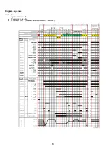
Grain kit diagram
ATTENTION: avoid the ignition and detection electrodes to contact metallic parts (blast tube, head, etc.), other-
wise the boiler’s operation would be compromised. Check the electrodes position after any intervention on the
combustion head.
15
14
3
1
3
8
EA:
Ignition electrode
ER:
Detection electrode
E115X, E150X, E180X
- MG
0
1
2
3
4
5
6
7
35
34
33
32
31
30
8
15
14
9
10
11
12
13
17
18
19
20
16
21
22
23
24
25
26
28
29
27
A
A
B
B
C
C
D
D
E
E
0
1
2
3
4
5
6
7
35
34
33
32
31
30
8
15
14
9
10
11
12
13
17
18
19
20
16
21
22
23
24
25
26
28
29
27
30 mg
36
Holes
27
Open air holes
50/80 mg
36
Holes
9
Open air holes
A
Gas pipe holes
B
Electrode holes
C
Open holes in diffuser air holes
D
Closed holes at diffuser air holes
E
Set screws for disk and cap on M3 hole