background image

12 

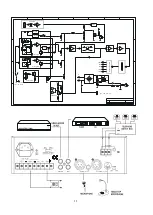
Mains Connection 

The supply transformer has been designed for use either 115Vac or 230Vac, 
Selected by slide switch on rear panel. The amplifier is factory set at 230Vac mains 
Voltage. 


Battery Connection(12Vdc for 20w / 40w, 24Vdc for 60w) 

When using external batteries, earth the amplifier via the screw terminal because of the high 
voltages present. Electrical stability of the system is increased by earthing the case. 

NOTE: 

The connection cable must be fitted with an in-line fuse,quick blow type

(20W : 6.3A, 

40W :10A , 60W : 8A). When connecting batteries please ensure correct polarity. 
 

Microphone Connections 

Mic1 input is either a balanced standard 1/4” stereo jack on the front panel or XLR and DIN 
on the rear panel (With selectable phantom power). Wiring is as follows: 


XLR (Balanced Operation) 

    Pin1 : Screen                                                 

Pin2 : Signal (live) 

Pin3 : Signal (return)   


DIN (Balanced operation) 


Pin1 : Signal (live) 

Pin2 :    GND   

    Pin3 : Signal (return) 

    Pin4 : Priority Control 

    Pin5 :    GND 


1/4” Stereo Jack Plug (Balanced operation) 


Tip : Signal (live)   

    Ring : Signal (return) 

    Sleeve : Screen 


Mic1 input has VOX priority which will override Mic2 and Aux input signals but   
NOT the TEL/EMER input. 
 
Mic1-2 input are XLR,DIN and phone jack with selectable phantom power located on the 
rear panel and wired as above. The phantom power is factory set and be enabled as 
follows: 

1.  Remove power lead from the AC wall socket. 
2. Remove top cover. 
3. Locate the link pins (Marked SW102) on the PCB behind microphone XLR input socket. 
4. connect the black shorting plug to the centre pin and ON position to enable the phantom 

power 


Chime 

Swithing on the manual chime on/off switch on the rear panel and short the pin4, pin5 of DIN 
Socket or short the sleeve and ring of phone plug-Mic1 will activate the chime function 
(“Ding-Dong” attention signal preceding a call).The default volume of the chime is pre-set at the 
factory and is adequate for most applications.) 


1

4

2

5

3


2

1

3


Summary of Contents for 2000 Series

Page 1: ...1 SERIE 2000 ELA Verst rker Bedienungsanleitung ELA Mischverst rker UMA 2040...

Page 2: ...keine Hornlautsprecher es sei denn sie sind speziell f r diesen Zweck konzipiert Vermeiden Sie das Anflicken von Lautsprecherleitungen Sollte es unvermeidlich sein verwenden Sie am besten eine gut ges...

Page 3: ...icht 11 10 15 13 14 9 8 7 6 5 4 3 2 1 12 1 Gleichspannungsanschluss 24V 9 Gong ein aus 2 Lautsprecheranschluss 10 AC Sicherungshalter 3 Line Ausgang 2 x RCA 11 Anschluss f Netzkabel 4 Aux Eingang 2 x...

Page 4: ...Size A3 Date 7 May 2002 Sheet of File A PBL2000 SCH Drawn By 3 2 1 3 2 1 2 5 3 1 4 MUTE CHIME VOX VOX POWER AMP OUTPUT BOARD 100V 70V 25V 8ohm COM 115V 230V DC 24V OR 12V _ G B 16V OR 10V PHANTOM POWE...

Page 5: ...weder einen Klinken oder einen XLR Stecker Die Anschlussbelegungen sind wie folgt XLR symmetrischer Betrieb Pin1 Abschirmung Pin2 Signal Pin3 Signal DIN symmetrischer Betrieb Pin1 Signal Pin2 Masse Pi...

Page 6: ...ebr ckt sind so dass auch Stereoquellen ohne Verwendung eines Spezialkabels verwendet werden k nnen Pr fen Sie bitte vor Anschluss einer Stereoquelle dass durch die Parallelschaltung von rechtem und l...

Page 7: ...uschspannungsabstand Alle Eing einsteller Linksanschlag 75dB unter Nennleistung Mic1 2 60dB unter Nennleistung Aux 70dB unter Nennleistung TEL 70dB unter Nennleistung Klangeinsteller Bass 10 dB at 10...

Page 8: ...8 PUBLIC ADDRESS SERIES 2000 AMPLIFIER Installation and User Instructions Cover Models Mixer Amplifier UMA 2040...

Page 9: ...rminating into a balanced input on long microphone cable runs ALWAYS use a mains grade double insulated cable for the loudspeaker cable runs ENSURE that all loudspeakers are in phase ENSURE that there...

Page 10: ...L 11 10 15 13 14 9 8 7 6 5 4 3 2 1 12 1 DC power supply terminals 9 Chime on off switch 2 Loudspeaker output terminals 10 AC fuse holder 3 Line output 2 x RCA phono 11 Mains input socket 4 Aux input 2...

Page 11: ...Size A3 Date 7 May 2002 Sheet of File A PBL2000 SCH Drawn By 3 2 1 3 2 1 2 5 3 1 4 MUTE CHIME VOX VOX POWER AMP OUTPUT BOARD 100V 70V 25V 8ohm COM 115V 230V DC 24V OR 12V _ G B 16V OR 10V PHANTOM POW...

Page 12: ...ced operation Pin1 Signal live Pin2 GND Pin3 Signal return Pin4 Priority Control Pin5 GND 1 4 Stereo Jack Plug Balanced operation Tip Signal live Ring Signal return Sleeve Screen Mic1 input has VOX pr...

Page 13: ...aker Connection This equipment provides four different types of loudspeaker output these are 100V 70V 25V line and low impedance you can only use one of these output at any one time any attempt to use...

Page 14: ...W 75dB below rated power Mic1 2 60dB below rated power Aux 70dB below rated power TEL 70dB below rated power Tone Controls Bass 10 dB at 100Hz Treble 10 dB at 10KHz Controls Mic1 Mic2 volume control...

Page 15: ...15...

Reviews: