background image

5

Getting Started

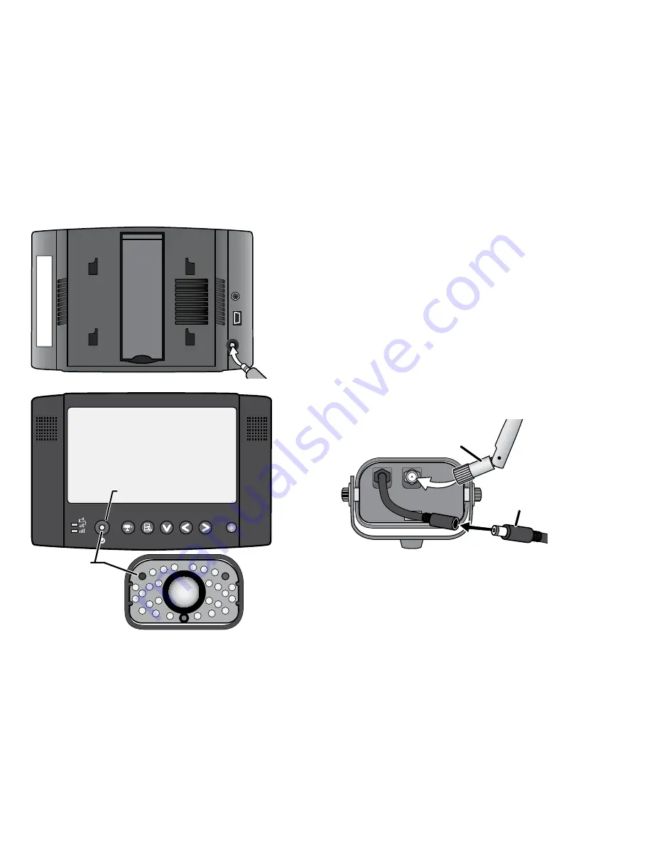
Connect the Power

Connect the receiver

Connect a standard AC adapter to the receiver’s power input.

Connect the outdoor camera 

1.  Attach an antenna to the rear of each camera 

and connect an AC adapter to the camera’s 
power input pigtail. (If necessary, connect the 
extension cord to the camera’s pigtail and 
connect the AC adapter to the extension cord.)   

2.  Connect the other end of each adapter to a 120 

volt AC (standard indoor) power outlet, and 
press the 

POWER

 button on the front of the 

receiver or on the remote control. 

Registration Name: Registration Code:

Antenna

AC Adapter

Power status


lights

POWER

 button

Summary of Contents for UDW20553

Page 1: ...replacement part or accessory Parts Department 800 554 3988 need special help due to a disability Accessibility Help Line 800 874 9314 voice or TTY During regular business hours Central Standard Time...

Page 2: ...fire electric shock and injury to persons including the following This equipment is NOT waterproof DO NOT expose it to rain or moisture DO NOT immerse any part of the product in water Do not use this...

Page 3: ...y children under the age of 13 If you are between the ages of 13 and 18 review these terms conditions and safety warnings with your parents or guardian to make sure that you and your parent or guardia...

Page 4: ...Using Zoom Mode 16 Pan and tilt in zoom mode 16 Understanding Night Vision 16 Connecting to Your TV 17 Reducing pixellation 17 Multiple Camera Features 18 Pairing Cameras 18 Some things to know about...

Page 5: ...dapter to the camera s power input pigtail If necessary connect the extension cord to the camera s pigtail and connect the AC adapter to the extension cord 2 Connect the other end of each adapter to a...

Page 6: ...onnecting the AC adapter seeing if the power outlet is controlled by a wall switch Check the Video Signal As soon as the receiver powers on it detects the camera and shows the video on the display The...

Page 7: ...3 or 4 The video is currently zoomed in If Try the signal status icon shows no bars or the display says No Signal making sure the camera is turned on re pairing the camera and receiver see page 18 th...

Page 8: ...ff The camera is off Link status Flashing The camera is in pairing mode Green The camera is connected to the receiver Off The camera is in standby Using the Camera Stand You can mount the camera with...

Page 9: ...angle then replace and tighten the bolts Mount the stand 1 Hold the base of the camera stand where you want to mount it and mark the location of the screw holes 2 Use the included screws and anchors...

Page 10: ...door camera you can move the sun shield forward to provide more shade for the lens If the top of the picture is cut off try moving the sun shield back To adjust the sun shield loosen the bolts on the...

Page 11: ...Camera What the buttons and LEDs do Button What it does POWER Turn the camera on Press and hold to turn it off Link Enter pairing mode LINK POWER Power connector Link status LINK Antenna Stand Lens Ba...

Page 12: ...ged Using the camera mount The indoor camera has a built in stand so you can place it on any flat surface If you want to place your camera on a wall or a ceiling or even if you just want to secure it...

Page 13: ...ver on Press and hold to turn it off SELECT CAMERA Cycle through the active cameras and quad display From the pairing menu link to the selected camera MENU ok Open and close the menu OK Speakers Anten...

Page 14: ...top of the zoom area In the menu move the cursor up one line In quad display go to channel 1 Zoom Enter and exit zoom mode What the lights mean Light State What it means Power status On The receiver...

Page 15: ...Change the video output format from NTSC North America to PAL Europe Power Save Turn on power save mode If you set this field to Auto the display turns off if it s idle for more than one minute The au...

Page 16: ...ures are only available in zoom mode Understanding Night Vision The weatherproof camera s included with your receiver has 24 infrared LEDs for low light conditions The infrared LED automatically turns...

Page 17: ...ys or plasma screens Reducing pixellation When video is put on a very large screen you can often see the edges of each pixel in the image There are a few ways to reduce the amount of pixellation on yo...

Page 18: ...utton varies from camera to camera see the manual that came with your camera 6 On the receiver open the menu 7 Scroll down to CAM1 through CAM4 and select the channel assigned to the new camera 8 Use...

Page 19: ...the receiver goes to the next enabled channel regardless of whether there is a camera present on that channel If there is no camera signal on a particular channel the receiver shows a black screen wit...

Page 20: ...urrently selected channel then scans the remaining channels in order The receiver will only scan channels that are enabled in the menu The receiver does not go into quad display during a scan If you p...

Page 21: ...is disabled or there is no signal from the camera that channel s section of the quad display will be blank To enter quad display 1 Open the menu 2 Scroll down to select Scan time 3 Use Right or Left t...

Page 22: ...your television The receiver brightness setting does not affect the television The image does not fit my TV screen Changing the TV out setting on the receiver in the system setup sub menu The display...

Page 23: ...hat might reflect the signal Avoid placing the camera and receiver where the signal path crosses a high traffic area or body of water For example place the camera on the same side of a hallway as the...

Page 24: ...other radio based wireless devices such as cordless telephones wireless controllers or wireless headphones or speakers large florescent light fixtures especially if they give off a buzzing noise worki...

Page 25: ...are not responding The image on the screen is frozen and resetting the camera did not help To reset the camera or receiver unplug the AC adapter Wait at least 15 seconds then reconnect the AC adapter...

Page 26: ...x 19 mm 220 x 145 x 36 mm Operating temperature 10 C 14 F to 50 C 122 F Input voltage 100 240 V AC 60 or 50 Hz Operating voltage 5 V DC 1 Amp 5 V DC 1 Amp 5 V DC 1 Amp Low light solution 24 IR LEDs 1...

Page 27: ...ng and Disposal Information Do not dispose of electronic devices or any of their components especially batteries and LCD displays in your municipal trash collection Consult your local waste management...

Page 28: ...hnical specifications were met Operation is subject to the following two conditions 1 this device may not cause interference and 2 this device must accept any interference including interference that...

Page 29: ...PARTICULAR PURPOSE THIS WARRANTY DOES NOT COVER OR PROVIDE FOR THE REIMBURSEMENT OR PAYMENT OF INCIDENTAL OR CONSEQUENTIAL DAMAGES Some states do not allow this exclusion or limitation of incidental...

Page 30: ......

Reviews: