background image

Be sure to thoroughly read the following items before you start using this product to ensure safe and correct 

use.

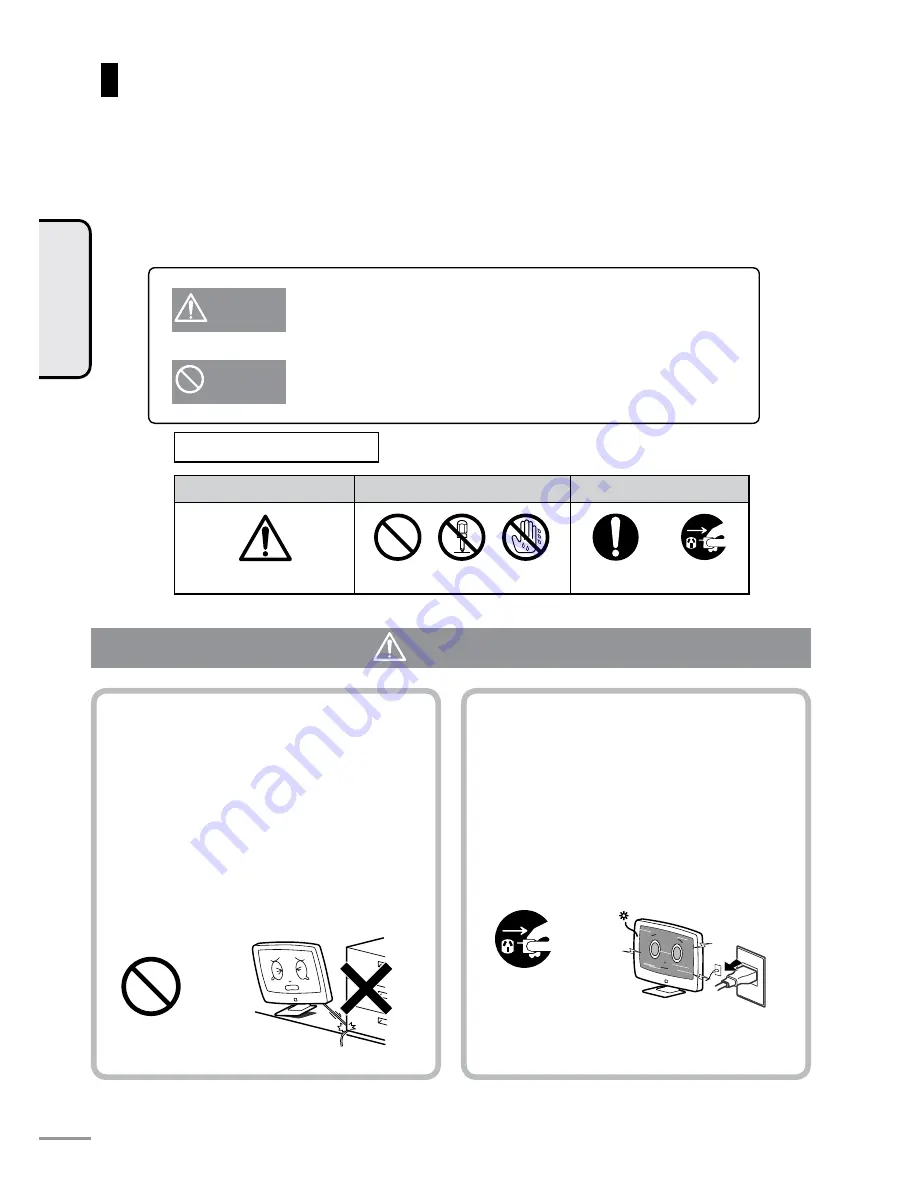
The following symbols indicate warnings in this 

 Owner’s Manual

 and on this product. Be sure to properly under-

stand the meanings of these symbols before reading this 

 Owner’s Manual

Safety Precautions

WARNING

WARNING

This symbol alerts the user to the risk of death or serious injury from fire 

or electric shock. 

CAUTION

This symbol alerts the user to the risk of injury or damage to nearby 

objects.

Symbol urging caution

General caution

Symbol indicating 

Caution

Do not 

disassemble

Do not handle with 

Wet hands to avoid 

risk of shock

General instruction

Unplug the 

power cord

Description of Symbols

Symbol indicating Caution

Symbol instructing an action

WARNING

Do not damage the power cord. 

Failure to do so may cause fire or electric 

shock. 

•  Do not pinch the power cord between this 

  product and the wall or floor during 

  installation.
•  Do not modify or damage the power cord.
•  Do  not  place  heavy  objects  on  or  tug  the 

power cord.

•  Do not heat or bring the power cord close to 

heating equipment.

• When unplugging the power cord, be sure to 

hold it by its plug.

If  this  product  becomes  damaged  or  you 

find some abnormality, please unplug the 

power cord.

Failure to do so may cause fire or electric 

shock. 

•  If  you  drop  this  product  or  the  chassis  is 

damaged, turn the power off and unplug the 
power plug.

• If you notice smoke, strange odors, noise or 

any other abnormality, turn the power off and 
unplug the power plug. 

Caution

Unplug the 

power cord 

from the 

wall socket

INTRODUCTION

4

CAUTION

Summary of Contents for TL27WRA-W

Page 1: ...e from SRS Labs Inc Thank you for purchasing this product Before you begin using this product please read the Safety Precautions Failure to observe these precautions may cause injury to the user other...

Page 2: ...ng Optional Equipment HDMI 30 Using Optional Equipment TV VIDEO 31 Enjoying TV with Headphones 32 Chapter 4 TV SETTINGS Adjusting TV Settings menu screen 34 Menu Flow Chart 35 Video Setup 36 Mode 36 C...

Page 3: ...INTRODUCTION Chapter 1 INTRODUCTION...

Page 4: ...scription of Symbols Symbol indicating Caution Symbol instructing an action WARNING Do not damage the power cord Failure to do so may cause fire or electric shock Do not pinch the power cord between t...

Page 5: ...ch the TV antenna wire or power plug WARNING Caution Do not disassemble Do not touch Insert the wall plug An incomplete insertion may generate heat or cause dirt or dust to accumulate resulting in fir...

Page 6: ...th cloth Doing so may cause heat to build up inside resulting in fire Caution Caution Caution Safety Precautions continued Do not install this product on unstable surfaces Doing so may cause it to fal...

Page 7: ...lure to do so may cause fire When inserting batteries make sure that the poles are facing the correct direction Failure to do so might cause the batteries to rupture and battery fluid to leak resultin...

Page 8: ...ntenna if necessary as it is exposed to the wind and rain The antenna is particularly susceptible to damage in loca tions subject to smoke and soot or locations exposed to sea breezes If video recepti...

Page 9: ...or location smears may appear in the picture or the picture may be delayed on screen This is not a malfunction These phenomena improve as room temperature is restored Do not install this product in lo...

Page 10: ...y Also do not use this product for an extended period of time with products made of rubber or vinyl in direct contact with the chassis Doing so may deform the chassis as a result of action of the plas...

Page 11: ...SET UP Chapter 2 SET UP...

Page 12: ...and may vary from image shown Accessories Power cord 1 pc Remote control 1 pc BACK ENTER MUTE POWER SLEEP TV VIDEO DISPLAY WIDE MODE HDMI AUDIO VOL CH MENU OK RESET FREEZE 0 This Owner s Manual 1 pc...

Page 13: ...their factory settings OK button page 36 This button confirms the se lected onscreen option Screen DISPLAY button page 26 This button selects how channels and the audio mode are displayed POWER butto...

Page 14: ...the same functions as the buttons on the remote control TV Remote control VIDEO 1 2 input S VIDEO input Video input Left monaural audio input Right audio input VIDEO 3 4 input Component Y input Compon...

Page 15: ...ct sunlight or bright overhead lighting falls on the remote control IR receiver on the TV Either re orient the lighting or TV or bring the remote control closer to the remote control IR receiver Do no...

Page 16: ...mercially available antenna cable or cable adaptor accord ing to the antenna jack you are using and connect the other end to the antenna input jack on the TV Wall antenna jack Antenna cable provided A...

Page 17: ...et The standby indicator on the front lights red Connecting the Power Cord When the TV is not in use for extended periods of time be sure to unplug the power plug from the power outlet Note Be sure to...

Page 18: ...the TV or POWER on the remote control The TV turns on and the country selec tion screen is displayed 2 Select either Australia or New Zealand using the cursor buttons on the remote control and press...

Page 19: ...V is turned on The automatic channel setup program can also be run from the channel setup menu page 39 You can also check how channels have been assigned If you turn the TV off before automatic channe...

Page 20: ...necting Other Equipment When no other equipment is to be connected proceed to Chapter 3 Watching TV page 24 You can start enjoying TV programs right away VIDEO 1 input This input is used for connectin...

Page 21: ...ilable DVI only supplies a video signal so connect audio cable too If connecting from DVI source to the HDMI1 jack connect audio to the Audio3 jack If connecting to the HDMI2 jack connect audio to the...

Page 22: ...left and right Take care not to pinch the cords Arranging the cables Pass the cable through the notch in the cover The cover can also be removed 22 SET UP Press down here Pull this way cover tabs 37...

Page 23: ...WATCHING TV Chapter 3 WATCHING TV...

Page 24: ...elect the desired channel To receive terrestrial broadcasts Select the desired channel using the number buttons or channel selection buttons Adjust the volume Adjust the volume using the volume button...

Page 25: ...umbers maps and recipes Press the FREEZE button The image that was displayed appears at the bottom right of the screen To delete a screen freeze press the FREEZE button again Screen freezes are automa...

Page 26: ...the screen The audio mode is not displayed when an external input is selected page 31 To turn the display off press the DISPLAY button again If you press the DISPLAY button the number label and inform...

Page 27: ...can select between main and sub audio in the case of dual language broadcasts such as English and another language broadcast If the broadcast is not a dual language broadcast pressing the AUDIO button...

Page 28: ...re expanded to naturally fill the entire screen In the Normal screen mode a black band containing no image appears on the left and right of the picture Panorama display cannot be selected when the vid...

Page 29: ...r is canceled when the TV is turned off If you press the SLEEP button with the sleep timer already set the time you set is added to the remaining time For example when the remaining time is 1 to 30 mi...

Page 30: ...h as DVD player or Digital Tuner connected by HDMI you can select as follows Press the HDMI button Each press on this button switches between HDMI1 and HDMI2 Press the TV VIDEO button to change from H...

Page 31: ...operation Switching of screens or volume adjustment is performed by the remote control for this TV Perform other operations according to the instructions in the user s guides for any optional device c...

Page 32: ...cially available headphones connect the headphones plug to the headphone jack at the bottom of the TV Insert the headphones plug as far as it can go An incomplete connection may cause audio to be outp...

Page 33: ...TV SETTINGS Chapter 4 TV SETTINGS...

Page 34: ...2 Press the MENU button to display the menu Press the buttons to select the menu icon containing the items you want to set up The currently selected icon is displayed in green While a menu icon is dis...

Page 35: ...Sharpness 5 levels 2 to 2 Color Temp Neutral Warm Cool Audio page 37 Audio setup menu Bass 32 levels Treble 32 levels Balance 32 levels Stereo Mono Auto Mono Main Sub Main Sub Main Sub SRS TruSurroun...

Page 36: ...cture Movie Picture ideal for watching movies Personal For making favorite settings Mode Select the desired setup item using the button in the sub menu Each of the settings can be changed by the butto...

Page 37: ...round XT function is used you can enjoy enhanced audio similar to the sound that you might experience in a movie theater SRS TruSurround XT is a virtual surround tech nology developed by SRS Labs Inc...

Page 38: ...th the screen setup icon selected sub menu items Standard mode and Vertical Center return to their factory settings 38 TV SETTINGS Current Mode This option switches the screen between Full Normal Pano...

Page 39: ...menu Auto Program If you select Auto Program in the sub menu the following message is displayed and you can select whether to execute Yes or cancel execution of the automatic channel setup program No...

Page 40: ...t Customize label name Use the cursor buttons to highlight desired item then press the button to begin edit To Edit the channel Label Select the channel number using the buttons Select the Label optio...

Page 41: ...DISPLAY Example of assigned equipment Not set Standard names VIDEO 1 VIDEO 2 VIDEO 3 VIDEO 4 HDMI1 or HDMI2 are used DVD DVD player recorder DVD1 DVD player recorder 1 DVD2 DVD player recorder 2 VCR V...

Page 42: ...essing the buttons switches between Australia and New Zealand If you change the country setting to other than the country you are in then broadcast channels may not tune in properly Resetting settings...

Page 43: ...REFERENCE Chapter 5 REFERENCE...

Page 44: ...I input 2 lines audio output Operating temperature 0 40 C Power requirements 230 240V AC 50Hz 120 W 140 W 190W 250W During standby 0 3 W 0 3 W 0 3W 0 3W Including table stand 75 0 cm W 86 3 cm W 97 5...

Page 45: ...Probable Cause Page No video or audio output Is the power plug disconnected from the power outlet Have you selected an input jack that is not connected to optional equipment Have you pressed the power...

Page 46: ...have reached the end of their service life Is bright light from a fluorescent lamp falling on the remote control IR receiver Picture is not sharp Picture flickers A probable cause is poor reception I...

Page 47: ...tly wipe off the dirt Wiping heavily may leave scratches on the surface of the panel Wipe off dust from the panel surface using a commercially available anti dust static removal brush To protect the p...

Page 48: ...36 DISPLAY 26 Dual language broadcast 27 DVI jack 21 DVD player 21 H I L M HDMI 30 HDMI jack 20 Headphone jack 32 Initial setting 18 INPUT 31 Language setting 18 Menu screen 34 Mute 24 O R S T Organiz...

Page 49: ...49 REFERENCE Memo...

Page 50: ...00 366 895 Monday through Friday 8 30am to 5 00pm The Customer Service Line is closed Saturday Sundays and public holidays For New Zealand www uniden co nz or call our Customer Service Hotline at 0800...

Page 51: ...nt or parts or as part of a system not manufactured by Uniden or F installed pro grammed or serviced by anyone other than an authorized Uniden Repair Agent or G Where the Serial Number label of the pr...

Page 52: ...his Owner s Manual is subject to change without notice Unauthorized duplication or copying of the content of this Owner s Manual is forbidden 2006 Uniden Australia Pty Ltd Uniden NZ Ltd Printed in Chi...

Reviews: