background image

7

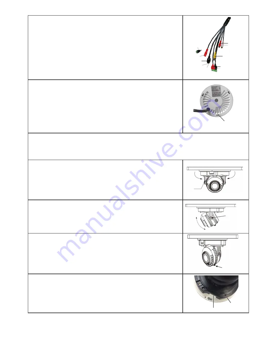
5.  If you have a 4K TPD camera, connect the plugs from the 

network cable tail to their appropriate cables.

When using an optional external power supply, the AC 

socket outlet shall be installed near the equipment and be 

easily accessible.

If installed outdoors, the cable and all cable connections 

must be routed inside the wall.

White - Audio Out

Red - Audio In

Yellow - Video (BNC)

Black - Alarm In

Red - Alarm Out

RJ45

Red - 12VDC (optional)

Network 

Activity 

LEDs

PoE

2.1mm Barrel Adapter 

NOTE:  12VDC power supply 

not included

6.  Align the camera base screw holes to the screws. Hang the 

base onto the screws then slide the base along the screw lock 

to secure. 

Screw Hole 

and Lock

7. 

Remove the protective films from the inside and outside of the camera dome and clean the 

dome with a microfiber cloth (not included) if available. 

Do not use a paper towel to clean the camera lens or dome as it might leave 

scratches.

8. 

Adjust the bracket to swivel the camera up to 175˚ on a 

horizontal axis (orients the camera for top/bottom of frame). 

Bracket

Swivel 

Direction

Swivel 

Direction

9. 

Loosen screw 1 and adjust the camera from 15 - 90˚ on a 

vertical axis. 

15˚ - 90˚

Screw 1

10. 

Loosen screw 2 to fine-tune the horizontal axis (

+/-

 30˚).

As you adjust the camera position, check it through the 

NVR Preview screen.

Screw 2

11. Insert an SD card if needed.

SD Card Slot

Reset Button

Summary of Contents for 4KTPD-MVF

Page 1: ... CAMERA INSTALLATION GUIDE 4KTPD MVF 4MTPD MVF 4MTPD 2 8 2MTPD VF 4MMD 2 8 2MMD 2 8 4MED 3 6 2MED 3 6 2018 Uniden America Corporation Irving Texas Issue 1 April 2018 2MTD 2 8 4KB MVF 4MB MVF 2MB VF 4MB 3 6 2MB 3 6 ...

Page 2: ... and federal law For further information on video surveillance and audio recording legal requirements please consult your local state and federal officials Uniden constantly works on improving our products This includes updating our documentation with the latest firmware changes Go to www uniden com to find the latest version of all documentation 2018 Uniden America Corporation All rights reserved...

Page 3: ... TURRET DOME CAMERA 10 What s Included 10 Install Camera 10 INSTALL LARGE BULLET CAMERAS 11 What s Included 11 Install Camera 12 INSTALL SMALL BULLET CAMERAS 12 What s Included 12 Install Camera 13 CONNECTING THROUGH PC 13 USING DEVICEMANAGER TOOL 13 WEB ACCESS 14 Set Security Levels 15 UNIDEN PROSERIES MOBILEPHONE CLIENT 16 SOFTWARE OPERATING 16 Add device 17 SPECIFICATIONS 18 TAMPER PROOF DOME C...

Page 4: ...4 TURRET DOME AND LARGE BULLET CAMERAS 20 SMALL BULLET CAMERAS 21 COMPLIANCE 22 FCC PART 15 22 IC 23 THREE YEAR LIMITED WARRANTY 23 ...

Page 5: ...most cameras are designed to operate between 14 F to 122 F 10 C to 50 C with a relative humidity of up to 95 Avoid installing cameras in direct sunlight and consider wind chill and other environmental factors too Mount the camera in an area that is visible but out of reach Route the wiring so it does not interfere with power or telephone cable lines and it should not be where it could be easily cu...

Page 6: ...ocation where you want it mounted Check the display on the monitor to verify that the view from that location is acceptable 2 Mount the camera s to the desired surface using the parts in the supplied mounting kit If mounting on drywall use the drywall anchors supplied in the kit 3 Adjust the camera to ensure that the camera has a satisfactory view of the area you would like to monitor Cameras have...

Page 7: ... the base onto the screws then slide the base along the screw lock to secure Screw Hole and Lock 7 Remove the protective films from the inside and outside of the camera dome and clean the dome with a microfiber cloth not included if available Do not use a paper towel to clean the camera lens or dome as it might leave scratches 8 Adjust the bracket to swivel the camera up to 175 on a horizontal axi...

Page 8: ...e housing allowing the camera to separate from the housing and clear dome 4 Connect the camera s network cable tail to the house cabling through the 1 hole When using an optional external power supply the AC socket outlet shall be installed near the equipment and be easily accessible If installed outdoors the cable and all cable connections must be routed inside the wall RJ45 Red 12VDC optional Po...

Page 9: ...ten screws INSTALL EYEBALL DOME CAMERA What s Included IP camera Mounting template sticker Star tipped Allen wrench 2 wire to 2 1mm barrell plug for optional 12V DC power input Installation screws and anchors Dessicant package Install Camera 1 Remove the camera and installation items from the box Verify that all parts are there 2 Hold the camera and sleeve steady and unscrew the ring from the base...

Page 10: ...lastic envelope and position it inside the camera 8 Reassemble the camera sleeve and ring Position the assembly onto the base and adjust the camera to the correct viewing angle As you adjust the camera position check it through the NVR Preview screen 9 When the viewing angle is correct tighten the ring to the base As you tighten the ring keep adjusting the camera as needed INSTALL TURRET DOME CAME...

Page 11: ... must be routed inside the wall RJ45 Red 12VDC optional PoE 2 1mm Barrel Adapter NOTE 12VDC power supply not included 6 Reassemble the camera unit Remove the dessicant packet from the sealed plastic envelope and position it inside the camera unit 7 Screw the camera unit to the base securely enough to adjust the camera position Double check the position through the NVR Preview screen Use an oil fre...

Page 12: ...w the camera base into position When using an optional external power supply the AC socket outlet shall be installed near the equipment and be easily accessible If installed outdoors the cable and all cable connections must be routed inside the wall White Audio Out Red Audio In Yellow Video BNC Black Alarm In Red Alarm Out RJ45 Red 12VDC optional Network Activity LEDs PoE 2 1mm Barrel Adapter NOTE...

Page 13: ...re there 2 Position the installation template at the location wall ceiling etc Drill a 1 hole as indicated on the sticker and install the anchors provided 3 Thread the network cable tail through the grommet and connect it to the house cabling through the 1 hole Plug the grommet into the hole Using the screws provided screw the camera base into position When using an optional external power supply ...

Page 14: ...lect VMS CMS From the Video Management System screen select Download VMS to download the plugin USING DEVICEMANAGER TOOL 1 Open DeviceManager The main Device Manager screen displays 2 Check IPC then select Discover A list of IP cameras on the network displays DeviceManager IP Search Option DeviceManager IP Cameras Discovered NOTE This tool can also modify IP addresses when setting a network camera...

Page 15: ...ling the plugins input the network camera IP address again a login popup prompts you to set the password NOTE In order to improve network security the network camera password needs to be 8 16 alphanumeric characters NOTE Entering an incorrect password 3 times locks the camera for about 30 seconds Set Password Request Setting Password 3 After setting the password enter the login interface Input the...

Page 16: ...gement and log search NOTE This fully functional interface is displayed when SD card is inserted into the device If no SD card is inserted a simple interface of the device includes real time preview parameter configuration file management and log search except the video playback NOTE Under no plugins mode insert an SD card to display fully functional interface NOTE When the device is motorized len...

Page 17: ...assword modification Modifies the registered user password Local Login Can directly login without account device stores the information in the phone User Register The account is used for storing customer information and related device list in the cloud storage User Name User Name 1 Log in with a registered user name password Enter the Device List management interface ...

Page 18: ...t Connection mode There are two methods to create serial number and IP Domain direct connections The cloud method connects a device via serial number the IP Domain method is to connect device via traditional IP address or dynamic domain name and port Adopt serial number to add device for default click upper IP Domain to switch IP Domain method Note When selecting IP Domain mode to add device if it...

Page 19: ...nk 3 After completing settings click Confirm The system automatically pre connects to check whether device information validity If it is correct it automatically returns to the Device list If incorrect it will display an error message that you have to confirm and add again SPECIFICATIONS TAMPER PROOF DOME CAMERAS 4KTPD MVF 4MTPD MVF 4MTPD 2 8 2MTPD VF GENERAL IR Distance 100 Night Vision 12 IR LED...

Page 20: ...8W 6W 8W 7W Operating Temp 4 F 131 F 15 5 C 55 C 14 F 122 F 9 7 C 50 C Operating Humidity 0 90 Dimensions inch 4 61 L x 4 61 W x 3 39 H 4 61 L x 4 61 W x 2 6 H 4 72 L x 4 72 W x 3 87 H 4 72 L x 4 72 W x 3 87 H CAMERA Image Sensor 1 3 4MP progressive scan CMOS 1 2 9 SONY 2 07 MP Progressive scan Exmor CMOS Effective Pixels 2MP 2MP Max Resolution 1920 x 1080 1920 x 1080 2592 x 1520 1920 x 1080 Min I...

Page 21: ...24 L x 3 07 W x 3 66 H 10 35 L x 3 66 W x 3 76 H CAMERA Image Sensor 1 2 9 SONY 2 07 MP Progressive scan Exmor CMOS 1 2 5 8MP Progressive scan CMOS 1 3 4MP progressive scan CMOS 1 2 9 SONY 2 07 MP Progressive scan Exmor CMOS Effective Pixels 2MP 2MP Max Resolution 1920 x 1080 3840 x 2160 4MP 2592x1520 1920 x 1080 Min Illumination 0Lux F1 4 IR ON Color 0 06Lux F1 4 B W 0 01Lux F1 4 0Lux F1 4 IR on ...

Page 22: ... AGC OFF Output Model PAL NTSC adjustable COMPLIANCE FCC PART 15 The equipment has been tested and found to comply with the limits for a Class B device pursuant to Part 15 of the FCC rules These limits are designed to provide reasonable protection against harmful interference in a residential installation This equipment generates uses and can radiate radio frequency energy and if not installed and...

Page 23: ...license exempt RSSs Operation is subject to the following two conditions 1 this device may not cause interference and 2 this device must accept any interference including interference that may cause undesired operation of the device Cet appareil est conforme aux normes CNR d Industrie Canada destinés aux appareils radio exempts de licence Son fonctionnement est soumis aux deux conditions suivantes...

Page 24: ...IED OR ARISING BY OPERATION OF LAW INCLUDING BUT NOT LIMITED TO ANY IMPLIED WARRANTIES OF MERCHANTABILITY OR FITNESS FOR A PARTICULAR PURPOSE THIS WARRANTY DOES NOT COVER OR PROVIDE FOR THE REIMBURSEMENT OR PAYMENT OF INCIDENTAL OR CONSEQUENTIAL DAMAGES Some states do not allow this exclusion or limitation of incidental or consequential damages so the above limitation or exclusion may not apply to...

Reviews: