UM220 User Manual
8
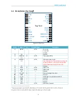
3.4
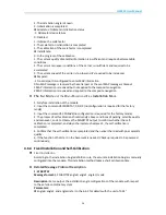
Pin Definition (Top View
)
NC
NC
TXD1
RXD1
VCC
TIME PULSE
WHEELTICK
NC
NC
FWD
NC
nRESET
VCC_RF
GND
RF_IN
GND
V_BCKP
GND
GND
NC
NC
TXD2
RXD2
NC
Top View
1
2
3
4
5
6
7
8
9
10
11
12
24
23
22
21
20
19
18
17
16
15
14
13
Figure 3-2 Top View
Pin No.
Name
I/O
Electrical Level
Description
1
nRESET
I
LVTTL
For reset
1=normal
0=reset
2
NC
—
—
Reserve
3
TIMEPUL
SE
O
LVTTL
Time pulse(1PPS)
4
WHEELTI
CK
I
LVTTL
Odometer speed pulse
Incorrect signals of the odometer will lead to
serious problems in the use of the product.
Please make sure the signal is correct.
5
NC
—
—
Reserve
6
TXD2
O
LVTTL
UART 2-TX
7
RXD2
I
LVTTL
UART 2-RX
8
NC
—
—
Reserve
9
VCC_RF
6
O
Output Voltage RF section
10
GND
—
—
Ground
11
RF_IN
I
—
GNSS signal input (BD2 B1+GPS L1)
12
GND
—
—
Ground
13
GND
—
—
Ground
14
NC
—
—
Reserve
15
FWD
I
LVTTL
Odometer forward
6
The maximum output current for VCC_RF is 60 mA,
with current limiting protection function. However,
long-term short circuit will still cause irreparable damage to the module.


