background image

16

RD1041K/RD1041Q/RD1041QD

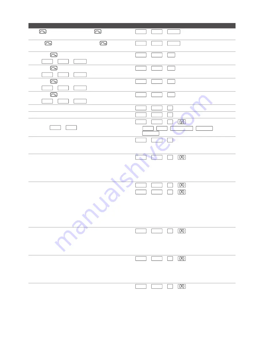
Command

Hotkeys

Bind 

 A (primary monitor) and 

 B (auxiliary 

monitor) switching

ScrLk + ScrLk + Insert

Unbind 

 A (primary monitor) and 

 B (auxiliary 

monitor) switching

ScrLk + ScrLk + Delete

Switch the 

 B (auxiliary monitor) to port1

(Press ScrLk + ScrLk + Delete to disable the binding)

ScrLk + ScrLk +

F9

Switch the 

 B (auxiliary monitor) to port2

(Press ScrLk + ScrLk + Delete to disable the binding)

ScrLk + ScrLk +

F10

Switch the 

 B (auxiliary monitor) to port3

(Press ScrLk + ScrLk + Delete to disable the binding)

ScrLk + ScrLk +

F11

Switch the 

 B (auxiliary monitor) to port4

(Press ScrLk + ScrLk + Delete to disable the binding)

ScrLk + ScrLk +

F12

Enable display mode menu

ScrLk + ScrLk + O

Switch PIP screen

ScrLk + ScrLk + W

Define hotkey preceding sequence 
(Default = ScrLk + ScrLk )

ScrLk + ScrLk + H +


y = ScrLk , CAPS , NUM LOCK ,  L CTRL

 和 

R CTRL

Enable/Disable the title bar 

ScrLk + ScrLk + T

Note that the settings of 

Show PC name

 and 

Show 

video signal

 on OSD menu will not be changed. 

Switch to Full view

ScrLk + ScrLk +

F

+

x = 1~4 (x=number button, corresponding to the 

connected PC port). The screen will remain the 

current display mode if the entered port number is 

no signal or alphabet.

Switch to PIP view

ScrLk + ScrLk + I +
ScrLk + ScrLk + P +

I = Main display, P = subordinate display
x = 1~4 (x=number button, corresponding to the 

connected PC port). The screen will remain the 

current display mode if the entered port number is 

no signal or alphabet. By default, the subordinate 

dispaly will be set to port 2.

Switch to Quad vide

ScrLk + ScrLk + Q +

x = 1~4 (x=number button, corresponding to the 

connected PC port). The frame of screen will be 

highlighted by red color after pressing. Disappear 

the highlighted after 5 seconds.

Switch to PAP view

ScrLk + ScrLk + A +

x = 1~4 (x=number button, corresponding to the 

connected PC port). The screen will remain the 

current display mode if the entered port number is 

no signal or alphabet.

Daisy Chain

ScrLk + ScrLk + K +

x = 1~8 (x=number of RD1041) Note that the audio 

and USB functions are only available on the first 

unit.

Summary of Contents for RD1041 Series

Page 1: ...User s Manual RD1041 Series 4 Port Quad View DVI USB KVM Switch Rev 1 1 Copyright All rights reserved...

Page 2: ...nect to computers 8 Daisy chain 8 Connect to USB devices 9 RS 232 control 9 Extension RD1041K only 10 Operation 11 Push button operation 11 OSD menu 11 PC selection 12 Display mode selection 12 Displa...

Page 3: ...er and receiver respectively They work in pair to extend KVM signal of RD1041K up to 100m using CAT5 cable More 100m can be extended if connecting a gigabit ethernet switch hub between transmitter and...

Page 4: ...m audio jack PC keyboard and mouse connector 4 x USB Type B female connector PC video connector 4 x DVI I female connector CAT5 port RJ 45 female connector PC audio connector 4 x 3 5 mm audio jack fem...

Page 5: ...ashes to indicate the USB connection may be incorrect Please check the USB connection between PC and this unit once the button is flashing Press and hold PC selection button 1 before turning on the po...

Page 6: ...nect console s DVI monitors audio USB mouse and keyboard respectively refer to the icons marked on the unit A primary monitor B auxiliary monitor 5 PC ports Connect to computers Each section comprises...

Page 7: ...it is depending on the models Connect to DVI monitors 1 Primary monitor 2 Auxiliary monitor Connecting same resolution and specification in both monitors are strongly recommended If two different reso...

Page 8: ...Connect to a computer s USB type A connector 2 Connect to a computer s audio out jack Daisy chain Connect to the RJ45 in connector of the first unit to the RJ45 out of second unit First unit s out to...

Page 9: ...y sending commands from a PC as well Please connect RS232 connector to a PC and plug the other end of RJ45 connector into RD1041 For more detailed operations refer to page 18 Please follow the table b...

Page 10: ...ly comprised of two units transmitter and receiver respectively For more details of extension please contact your local distributor Front Rear Front Rear 1 Connect from the unit to a Gigabit Ethernet...

Page 11: ...promptingyou to decide whether to ignore the same message in the future and yet you will find there is no mouse movement to disable this message So it is suggested that you should install your USB mo...

Page 12: ...ons on the unit directly Note that the B will be displayed by full view only Full view Displays the selected PC image by full screen PIP view Displays the PC images by picture in picture To switch the...

Page 13: ...f mouse on screen to select computer and double click to enlarge the image to full screen Full view To switch between different computers under full view mode press number button 1 4 to select a compu...

Page 14: ...ired samll screen on the right side using mouse cursor Double click left button of mouse to switch between PAP and full view 01 02 03 04 Daisy chain operation Before starting the daisy chain operation...

Page 15: ...ing is enabled ScrLk ScrLk Next higher port Joint select PC Audio USB hub and auxiliary if the binding is enabled ScrLk ScrLk Previous PC port Joint select PC Audio USB hub and auxiliary if the bindin...

Page 16: ...Show video signal on OSD menu will not be changed Switch to Full view ScrLk ScrLk F x 1 4 x number button corresponding to the connected PC port The screen will remain the current display mode if the...

Page 17: ...setup to No Switch between PIP screen I Bind A and B switching Home Bind the A primary monitor and B auxiliary monitor switching if the Bind auxiliary on OSD menu is setup to Yes Switch A primary moni...

Page 18: ...he PC name display Show video signal Yes No Enable Disable the current resolution display Next page Skip to the next page Output resolution Auto 1920x1200 1920x1080 12 80x1024 1024x768 1680x1050 1600x...

Page 19: ...Settings and then enter the following date Bits per second 115200 Date bits 8 Parity None Stop bits 1 Flow control None 3 Open Hyper Terminal and create a new connection Program Accessories Communica...

Page 20: ...ercial environment This equipment generates uses and can radiate radio frequency energy and if not installed and used in accordance with this User Guide may cause harmful interference to radio communi...

Reviews: