background image

20

HX120

Item

Sub-item

Option

Description

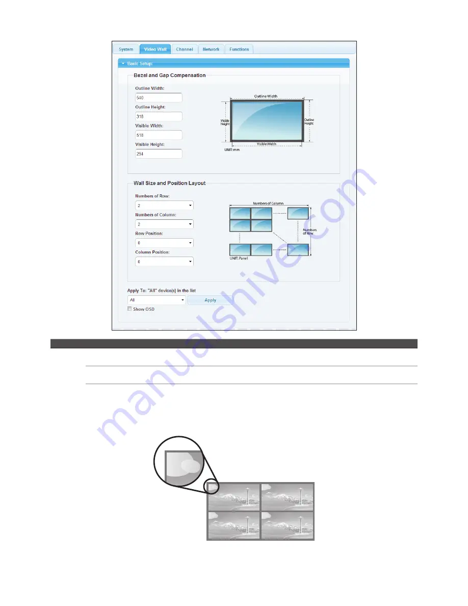
Video Wall Bezel and Gap 

Compensation

Adjust the compensation for bezel between panels.

Wall Size and Position 
Layout

Setup the display quantities, and specify the positions for each display.

Apply To "All" 
device(s) in the list

Apply the settings above to specify or all devices in the list. The screens will refresh after 
pressing Apply button. 

Show OSD: Enable/disable the display of number on each monitor. To sort the sequence of monitors, please configure the 

position of row and column. 

0

1

2

3

0

Summary of Contents for HX120T

Page 1: ...User s Manual HX120T R W HDMI AV Matrix Extender Video Wall Version 1 1...

Page 2: ...t to multipoint 8 Video Wall 8 Matrix connection 8 Bi directional IR connection 9 Remote control 10 HDMI CEC remote 10 Remote control optional 10 RS 232 control 11 Operation 12 Control manually 12 Set...

Page 3: ...r local PC or source by using single Cat5 cable transmission For convenience of control the IR is built in and the connected AV device can be remote from either end of connection In additional RS232 U...

Page 4: ...RJ45 via HDMI via HDMI RS 232 Extension Support Yes Yes Yes Ethernet Connectors Yes Yes Yes Cable media CAT5e CAT6 CAT5e CAT6 CAT5e CAT6 Power LED 1 Red 1 Red 1 Red Video LED 1 Green 1 Green 1 Green D...

Page 5: ...e EDID of connected monitor To update the EDID remove the Receiver s power Hold the device button and then power on the unit Release the Device button when the Power indicator flashes 4 IR receiver Co...

Page 6: ...Frame is required other specs like IGMP Snooping IGMP Querier IGMP v2 and IGMP Fast Leave are strongly recommended If more than one transmitter connects to the same network segment without support of...

Page 7: ...ng a USB cable Connecting the local Transmitter and remote Receiver unit Point to point TV USB devices A V source or PC Receiver Transmitter To connect the Transmitter and Receiver simply connect both...

Page 8: ...x8 using a single Cat5 cable Gigabit Ethernet Switch A V source or Receiver Video Wall x 9 PC Transmitter Matrix connection The HDMI AV Matrix Extender provides varied and flexible extension for diver...

Page 9: ...trol and the other end to the jack of IR RECEIVER remote or local unit of HDMI AV Matrix Extender Place the IR Emitter to somewhere face the IR receiver of A V source and the other end to the jack of...

Page 10: ...s of AV equipment For more details please refer to the corresponding instruction manual 3 Connect to a Gigabit Ethernet hub not included between Transmitter and Extender Receiver VideoWall Receiver if...

Page 11: ...oacl unit 1 Connect the RS232 connector to a PC and plug the other end of connector into the female connector of Transmitter 2 Connect the Transmitter and Receiver using Cat5 cable Alternatively the R...

Page 12: ...Setup from web user interface IP detection 1 Adjust the DIP switch of Transmitter and Receiver to the same position 2 Group the Transmitter and Extender Receiver VideoWall Receiver units to a network...

Page 13: ...ter and Extender Receiver VideoWall Receiver using web UI please follow the steps below to join the PC to the network Note The example shown here is using Windows 7 For other operating systems please...

Page 14: ...Click Internet Protocol Version 4 TCP IPv4 and then click Properties 7 Click Use the following IP address to specify an IP address that is on the same subnet as Transmitter Extender Receiver VideoWal...

Page 15: ...ation of unit Update Firmware Update the firmware The browser will be reloaded after updating Please contact the technical support if you have problem to upload Utilities Factory Default Restore to th...

Page 16: ...th the RS 232 device you have connected By default the system settings are as following Baudrate 115200 Data bits 8 Parity None Stop bits 1 Click the Apply once the baudrate settings have been changed...

Page 17: ...channel select has been ticked the channel will be saved and based on the selection of web page even the settings of DIP switch are different between Transmitter and Receiver If the option of Save cha...

Page 18: ...hannel OSD display Enable the display of channel number after the video connection has been established The channel number will be shown on the upper left of screen for a few seconds Turn Off Screen W...

Page 19: ...tion Display the information of unit Update Firmware Update the firmware The browser will be reloaded after updating Please contact the technical support if you have problem to upload Utilities Factor...

Page 20: ...e display quantities and specify the positions for each display Apply To All device s in the list Apply the settings above to specify or all devices in the list The screens will refresh after pressing...

Page 21: ...w The monitor number of row and up to 8 Numbers of Column The monitor number of column and up to 8 Row Position Specify the row position of monitor The row order from top to bottom is 0 7 Column Posit...

Page 22: ...lumn Position 0 0 1 Monitor 2 0 1 Numbers of Row 1 Numbers of Column 2 Row Position 0 Column Position 1 2x1 Video Wall example To duplicate the image on the Video Wall setup the Wall Size and Position...

Page 23: ...ed channel from the Transmitters Item Sub item Option Description Network IP Setup DHCP Static Select DHCP to obtain IP address automatically or select Static to assign an IP manually Device Mode Matr...

Page 24: ...p the baudrate settings Miscellaneous Settings Enable Channel OSD display Enable the display of channel number after the video connection has been established The channel number will be shown on the u...

Page 25: ...perations refer to the description below Remote control optional The description below is an example for switching between different channels The operation may vary depending on actual usage and conne...

Page 26: ...screen Press Up or Down button to select the desired source and then press OK 5 The screen will display to the new source you have selected Additional options Select Scan node to refresh if more devic...

Page 27: ...perated in a commercial environment This equipment generates uses and can radiate radio frequency energy and if not installed and used in accordance with this User Guide may cause harmful interference...

Page 28: ...http www uniclass com tw...

Reviews: