


15
Technical Features
ENGLISH
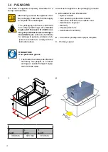
2.4 - OPERATING DATA
KON
m
R 18 - C 18
R 24 - C24
R 28 - C28 R 35 - C35
Nominal heat input in CH / DHW mode
kW
18,0 / 23,4
23,4 / 23,4
28,0 / 28,0
33,0 / 33,0
Minimum heat input with Nat. Gas / Propane
kW
3,0 / 4,4
3,0 / 4,4
4,4 / 5,6
4,4 / 5,6
Nominal heat output
kW
17,4
22,6
27,2
32,0
Minimum heat output
kW
2,9
2,9
4,3
4,3
Nominal output in condensation 50/30 °C
kW
18,4
24,0
28,9
33,8
Minimum heat output in condensation 50/30 °C
kW
3,2
3,2
4,7
4,7
Combustion efficiency at full load
%
97,6
97,2
97,6
97,2
Combustion efficiency at part load
%
98,6
98,6
98,1
98,1
Heat losses through the casing (min.-max.)
%
2,0 - 0,74
2,0 - 0,7
1,47 - 0,43
1,47 - 0,2
(*) Net flue gas temperature tf-ta (max.)
°C
49
57,6
48
57
Flue gas mass flow rate (min.-max)
g/s
1,3 - 7,9
1,34 - 10,3
2,0 - 12,5
2,0 - 14,7
Air excess λ
%
20,6
20,6
23,0
23,0
CO
2
%
9,5 - 9,5
9,5 - 9,5
9,3 - 9,3
9,3 - 9,3
CO at 0% of O
2
(min. - max)
ppm
10 - 95
10 - 107
19 - 98
15 - 108
Maximum production of condensate
kg/h
2,9
3,7
4,5
5,3
Chimney heat losses with burner ON (min. - max.)
%
1,4 - 2,4
1,4 - 2,6
1,9 - 2,4
1,9 - 2,8
Chimney heat losses with burner OFF
%
0,60
0,46
0,41
0,34
Prevalenza disponibile alla base del camino min. / max.
Pa
2 / 70
2 / 70
2 / 70
2 / 70
Notes: (*) Room Temperature = 20°C Data obtained with appliance operated with Nat Gas (G20)
For the adjustment data: NOZZLES - PRESSURES - DIAPHRAGMS - FLOW RATES - CONSUMPTIONS refer to the paragraph ADAPTATION TO OTHER TYPES OF GAS.
2.5 - GENERAL FEATURES
KONm
R 18 C 18
R 24
C 24 R 28 C 28 R 35 C35
Appliance category
II
2H3P
II
2H3P
II
2H3P
II
2H3P
Minimum heat. circuit output (∆t 20 °C)
l/min
1,2
1,2
1,7
1,7
Minimum heating circuit pressure
bar
0,5
0,5
0,5
0,5
Maximum heating circuit pressure
bar
3
3
3
3
Primary circuit content
l
2,2
2,2
2,8
2,8
Maximum operating temperature in heat.
°C
85
85
85
85
Minimum operating temperature in heat.
°C
30
30
30
30
Expansion vessel total capacity
l
8
8
10
10
Expansion vessel pre-load
bar
1
1
1
1
Maximum system capacity (max temp. calc.)
l
184
184
184
184
Minimum domestic hot water circuit flow rate
l/min.
-
2,0
-
2,0
-
2,0
-
2,0
Minimum domestic hot water circuit pressure
bar
-
0,5
-
0,5
-
0,5
-
0,5
Maximum domestic hot water circuit pressure
bar
-
6
-
6
-
6
-
6
Domestic hot water specific flow rate (∆t 30 °C) ‘‘
D
’’
l/min.
-
11,2
-
11,2
-
13
-
16
Production of D.H.W. in continuous operation with ∆t 45 K
l/min.
-
7,34
-
7,34
-
8,6
-
10,1
Production of D.H.W. in continuous operation with ∆t 40 K
l/min.
-
8,26
-
8,26
-
9,7
-
11,4
Production of D.H.W. in continuous operation with ∆t 35 K
l/min.
-
9,44
-
9,44
-
11,1
-
13,0
Production of D.H.W. in continuous operation with ∆t 30 K
l/min.
-
11,0
-
11,0
-
12,9
-
15,2
Production of D.H.W. in continuous operation with ∆t 25 K (*)
l/min.
-
13,2
-
13,2
-
15,5
-
18,3
Adjustable DHW temperature
°C
-
38-60
-
38-60
-
38-60
-
38-60
Voltage/Frequency electric power supply
V-Hz
230/50
230/50
230/50
230/50
Fuse on the power supply
A (F)
4
4
4
4
Protection rating
IP
X5D
X5D
X5D
X5D
Net weight
kg
32,5
34
32,5
34
35
36,5 35
36,5
Gross weight
kg
35,5 37
35,5
37
38
39,5 38
39,5
F Factor
-
1
-
1
-
2
-
2
R Factor
-
-
-
-
(*) mixed


