background image

15

Installation Instructions

ENGLISH


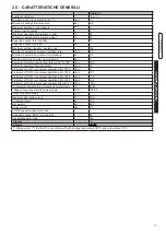
KON b 

P

depth

(mm)

L

width

(mm)

H

height

(mm)

Net 

Weight

(kg)

Gross

Weight

(kg)

28 

 640

730 

 960

70,5 

84,5

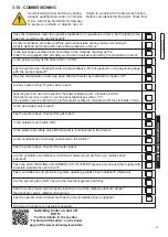
The 

KON  b 

boiler is supplied completely assembled 

in a sturdy cardboard box. 

After having removed the appliance from 

the packaging, make sure that the supply 

is complete and undamaged. 

The packaging elements (cardboard 

box, straps, plastic bags, etc.) 

must be 

kept out of the reach of children as 

they are potential sources of danger

.

Unical AG s.p.A. 

will not be held liable 

for damage to persons, animals or ob-

jects due to failure to comply with the 

instruction above.

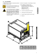
As well as the appliance, the packaging contains:

A  DOCUMENTATION ENVELOPE

  -  User operating instructions booklet

  -  Instruction booklet for the installer and   

  maintenance engineer

  -  2 Spare parts form 

  -  Certificate of conformity

B  -  Connection predisposition template

C  -  4 rawlplugs for boiler attachment

D  -  Flue gas exhaust collector (S version only)

E  -  Piping kit

3.4 - PACKAGING

Summary of Contents for KON

Page 1: ...I TA L I A N O E N G L I S H ISTRUZIONI PER L INSTALLATORE E IL MANUTENTORE INSTALLATION AND SERVICING MANUAL B 28 KON ...

Page 2: ...2 http www unicalag it prodotti domestico 50 condensazione gas kon 1275 kon b ...

Page 3: ...arametri modificabili da pannello comandi 30 4 3 Adattamento all utilizzo di altri gas 31 4 4 Note importanti 32 4 4 1 Funzione Antilegionella 32 4 5 Schema elettrico 33 4 6 Codici di errore 34 3 ISTRUZIONI PER L INSTALLATORE 14 3 1 Avvertenze generali 14 3 2 Norme per l installazione 14 3 3 Operazioni preventive di verifica e adeguamento impianto 14 3 4 Imballo 15 3 5 Posizionamento della caldaia...

Page 4: ...ali Questo apparecchio dovrà essere destinato solo all uso per il quale è stato espressamente previsto Ogni altro uso è da considerarsi improprio e quindi pericoloso 1 1 avvertenze generali Il libretto d istruzioni costituisce parte integrante ed essenziale del prodotto e dovrà essere conservato dall utente Leggere attentamente le avvertenze contenute nel libretto in quanto forniscono importanti i...

Page 5: ...uzioni nonché gli altri documenti relativi all apparecchio inseriti nella busta contenuta nell imballo L utente deve custodire tale documentazione in modo da poterla avere a disposizione per ogni ulteriore consultazione Informare l utente sull importanza delle bocchette di areazione e del sistema di scarico fumi evidenziandone l indispensabilità e l assoluto divieto di modifica Informare l utente ...

Page 6: ...erativa dell apparecchio ATTENZIONE Per stringere o allentare i raccordi a vite utilizzare esclusivamente delle chiavi a forcella chiavi fisse adeguate L utilizzo non conforme e o gli attrezzi non adeguati possono provocare dei danni per es fuoriuscite di acqua o di gas ATTENZIONE Indicazioni per apparecchi funzionanti a gas propano Sincerarsi che prima dell installazione dell apparecchio il serba...

Page 7: ...Potenza utile in condensazione 11 Qn Portata termica massima 12 Adjusted Qn Regolata per portata termica nominale 13 PMS Pressione max esercizio riscaldamento 14 T max Temperatura max riscaldamento B Caratteristiche circuito sanitario 15 Qnw Portata termica nominale in funzione sanitario se diversa da Qn 16 D Portata specifica A C S secondo EN625 EN13203 1 19 PMW Pressione max esercizio sanitario ...

Page 8: ...cqua negli impianti di riscaldamento deve essere compreso Per minimizzare la corrosione è fondamentale l uso di un inibitore di corrosione affinchè questo funzioni efficacemente le superfici metalliche devono risultare pulite vedi listino domestico sez ACCES SORI di protezione impianti VALORE MIN MAX PH 6 5 8 Durezza fr 9 15 NOTA Maggiori info nella sezione Info Tecniche alla pagina della caldaia ...

Page 9: ... A N O 2 CARATTERISTICHE TECNICHE E DIMENSIONI 2 1 CARATTERISTICHE TECNICHE 2 2 VISTA CON L INDICAZIONE DEI COMPONENTI PRINCIPALI E DIMENSIONI NOTA Per maggiori informazioni consultare Info Tecniche dal sito Vista dall alto Vista da sotto ...

Page 10: ...ettore fumi 24 Scambiatore Condensatore in alluminio 25 Valvola di sfiato 26 Sifone di scarico condensa 35 Trasformatore di accensione 41 Sonda sanitario 42 Vaso espansione sanitario 3 l 43 Bollitore 60 l 44 Valvola sicurezza sanitario 8 bar An Anodo C Uscita acqua calda sanitaria G G Ingresso gas G F Ingresso acqua fredda G M Mandata impianto riscaldamento G R Ritorno impianto riscaldamento G Rc ...

Page 11: ...Tecnhiche I TA L I A N O Prevalenza mH 2 O Portata l h 2 3 2 PRODUZIONE ACQUA CALDA SANITARIA 2 3 1 PORTATA PRESSIONE DISPONIBILE PER L INSTALLAZIONE 2 3 DIAGRAMMI 45 4 C 12 C 12 l min Tempo sec Temperatura di prelievo C ...

Page 12: ...ECONDO DIRETTIVA ErP Elemento Simbolo Unità KON B 28 Potenza utile nominale Pnominale kW 27 Efficienza energetica stagionale del riscaldamento d ambiente ƞs 93 Classe di efficienza stagionale per riscaldamento A Per le caldaie per il riscaldamentod ambiente e le caldaie miste potenza termica utile Potenza termica utile in regime di alta temperatura Tr 60 C Tm 80 C P4 kW 15 6 Rendimento alla potenz...

Page 13: ...rio bar 8 Portata specifica acqua sanitaria t 30 C D l min 18 4 Limitatore di portata sanitaria l min 12 Produzione di A C S in funz continuo con t 45 K l min 9 Produzione di A C S in funz continuo con t 40 K l min 10 1 Produzione di A C S in funz continuo con t 35 K l min 11 5 Produzione di A C S in funz continuo con t 30 K l min 13 4 Produzione diA C S in funz continuo con t 25 K l min 16 1 Temp...

Page 14: ...na fumaria Attenzione Se nel locale di installazione sono presenti polveri e o vapori aggressivi corrosivi l apparecchio deve essere adeguatamente protetto e deve poter funzionare indipendentemente dall aria del locale Attenzione Montare l apparecchio solo su una parete chiusa di materiale non infiam mabile piana verticale in modo che possano essere rispettate le distanze minime richieste per l in...

Page 15: ... di pericolo La Unical AG S p A declina ogni re sponsabilità nel caso di danni procurati a persone animali o cose subentranti in seguito a mancata osservanza di quanto sopra esposto Nell imballo oltre all apparecchio sono contenute A BUSTA DOCUMENTAZIONE Libretto istruzioni d uso per l utente Libretto istruzioni per l installatore e il manutentore Garanzia N 2 Cedole ricambi Certificato di conform...

Page 16: ...e non deve essere costi tuita da materiale infiammabile Poiché la temperatura della parete su cui è installata la caldaia e le temperatura del condotto di scarico coassiale non superano in funziona mento normale la temperatura am biente di oltre 60 K non è necessario rispettare distanze minime da pareti infiammabili Per le caldaie a condotti di aspira zione e scarico sdoppiati nel caso di pareti i...

Page 17: ...irazione LScarico COASSIALE Ø60 100 SDOPPIATO Ø80 DA m FINO A m DA m FINO A m 1 7 0 5 0 5 40 20A 20S COASSIALE Ø80 125 SDOPPIATO Ø60 DA m FINO A m DA m FINO A m 1 9 1 1 20 10A 10S Terminali verticali di scarico e aspirazione diretti all esterno mediante condotti di tipo coassiale op pure di tipo sdoppiato C53x C53 C53 NON AMMESSO C53 LUNGHEZZA TOTALE LAspirazione LScarico SDOPPIATO Ø80 SDOPPIATO Ø...

Page 18: ...l a ria comburente e scarico fumi mediante camino individuale o collettivo C93x C93 Collegamento aria fumi mediante condotti coas siali nel locale caldaia e monoparete nella canna fumaria aria comburente controcorrente nella canna fumaria NOTA Maggiori info nella sezione Info Tecniche alla pagina della caldaia nel sito www unicalag it C63x C63 Caldaia destinata ad essere collegata ad un siste ma d...

Page 19: ...nstallazione e nell uso e comunque per inosservanza delle istruzioni date dal costruttore stesso Adattatore per sistemi sdoppiati Attenzione Per tutte le configurazioni di scarico montare il distanziale camino fornito con la caldaia NOTA Per maggiori informazioni riguardo alle perdite di carico singoli compo nenti per informazioni riguardo alle norme alle regole e alle prescrizioni per un corretto...

Page 20: ...anni a persone animali e cose nei confronti dei quali il costruttore non può essere considerato responsabile Avvertendo odore di gas a Non azionare interruttori elettrici il telefono o qualsiasi altro oggetto che possa provocare scintille b Aprire immediatamente porte e finestre per creare una corrente d aria che purifichi il locale c Chiudere i rubinetti del gas M MANDATA 3 4 R RITORNO 3 4 G GAS ...

Page 21: ... vedi par 3 10 e portato in temperatura l impianto ar restare il funzionamento della caldaia e ripetere le operazioni di sfogo aria lasciare raffreddare l impianto e se nacessario riportare la pressione dell acqua a 0 8 1 bar Vedi par 4 4 Effettuati i collegamenti dell impianto procedere al riempimento del circuito Tale operazione deve essere effettuata con cautela rispettando le seguenti fasi apr...

Page 22: ...a che è necessario installare sulla linea di alimentazione elettrica della caldaia un interruttore bipolare con distanza tra i contatti maggiore di 3 mm di facile accesso in modo tale da rendere veloci e sicure eventuali operazioni di manutenzione La sostituzione del cavo di alimentazio ne deve essere effettuata da personale tecnico autorizzato UNICAL AG S p A utilizzando esclusivamente ricambi or...

Page 23: ...o al capitolo 3 7 eventuali saracinesche di intercettazione impianto sono aperte il gas da utilizzare corrisponde a quello di taratura della caldaia in caso contrario provvedere ad effettuare la conversione della caldaia all utilizzo del gas disponibile vedi sezione 4 3 tale operazione deve essere eseguita da personale tecnico qualificato secondo le norme vigenti il rubinetto di alimentazione del ...

Page 24: ...ONE DELLA funzione di taratura 3 11 2 Posizionamento delle sonde 1 ATTIVAZIONE Premendo il pulsante D per 3 secondi si attiva la funzione taratura Rilasciare quando compare simbolo SERVICE Non premere x più di 9 par 4 2 Tale funzione non si attiva in presenza di blocco o richiesta sanitaria 2 MASSIMA POTENZA Girando la manopola B al MAX la caldaia fun zionerà alla massima potenza 3 simboli illumin...

Page 25: ...i del terminale di aspirazione e scarico verificare che non vi siano perdite di gas 3 12 REGOLAZIONE DEL BRUCIATORE 2 Regolazione alla potenza minima Azionare la caldaia in modalità taratura alla MI NIMA POTENZA vedi 3 11 1 Una volta che il bruciatore è acceso controllare che il valore di CO2 MINIMO corrisponda a quello indicato nella tabella UGELLI PRESSIONI Correggere eventualmente il valore ruo...

Page 26: ...tenza avviam IG min max min max min max Gas nat G20 4 2 27 4 4 28 20 1400 6700 9 8 8 9 3 9 2 0 47m h 2 96 m h 60 Propano G31 5 3 27 5 6 28 37 1500 5800 9 8 8 10 7 10 7 0 34 kg h 2 17 kg h 60 i dati riportati sono riferiti al funzionamento in riscaldamento Non compreso per Svizzera In alcune zone potrebbero sussistere particolari condizioni di distribuzione del gas con una miscela tale da richieder...

Page 27: ...do il valore di Potenza percentuale del bruciatore 3 12 1 ADATTAMENTO DELLA POTENZA ALL IMPIANTO DI RISCALDAMENTO Es per depotenziare la caldaia a 24 kW modificare il parametro HP circa 85 Agire sul parametro HP par 4 2 parametri modi ficabili da pannello comandi per ottenere il valore corrispondente alla potenza desiderata L utente NON è autorizzato all attivazione della funzione di seguito descr...

Page 28: ... di entrata dell acqua fredda se chiuse in precedenza Sfiatare e se necessario procedere al ripristino della pressione dell impianto di riscaldamento fino a raggiungere una pressione di 0 8 1 0 bar Aprire la valvola intercettazione gas Dare Tensione alla caldaia Controllare la tenuta stagna dell apparecchio sia sul lato gas che sul lato dell acqua Rimontare il mantello frontale dell apparecchio Is...

Page 29: ...essostato di sicurezza contro la mancanza acqua 13 Il pressostato blocca la caldaia se la pressione d acqua è inferiore a 0 4 bar Senza richiesta chiudere i rubi netti di intercettazione del circuito di riscaldamento aprire il rubinetto di scarico per far scendere la pres sione d acqua Prima di rimettere in pressione verificare la pressio ne del vaso d espansione Vaso d espansione 8 riscaldamento ...

Page 30: ...30 TA 30 0 TA 0 POTENZA MASSIMA DI RISCALDAMENTO VALORI DA A STANDARD 0 Min 99 Max 99 PRERISCALDO VALORI DA A STANDARD 0 1 0 TEMPERATURA DELLA SONDA ESTERNA VALORI DA A STANDARD 0 20 C 30 10 C 20 0 C POST CIRCOLAZIONE DELLA POMPA VALORI DA A STANDARD 0 5 min 1 SEMPRE 0 5 min SELEZIONE Ruotare la manopola RISCALDAMENTO B MODIFICA VALORE Ruotare la manopola SANITARIO C Il valore lampeggia sul displa...

Page 31: ...batoio del gas sia stato disaerato Per una disaerazione a regola d arte del serbatoio rivolgersi al fornitore dei gas liquido e comunque a personale abilitato ai sensi di legge Se il serbatoio non è stato disaerato a regola d arte possono insorgere problemi di accensione In tal caso rivolgersi al fornitore del serbatoio del gas liquido Per la conversione della caldaia da un gas all al tro occorre ...

Page 32: ...trico per la partenza del bruciatore quando la pressione è inferiore a 0 4 bar La pressione dell acqua nell impianto di riscaldamento non deve essere inferiore a 0 8 1 bar in difetto agire sul rubinetto di carico di cui la caldaia è dotata L operazione deve essere effettuata ad impianto freddo Il manometro inserito in caldaia consente la lettura della pressione nel circuito NOTA Se la caldaia è st...

Page 33: ...za acqua E ACC RIL Elettrodo accensione rilevazione MVD Motore valvola deviatrice P Circolatore SR Sensore riscaldamento mandata SRR Sensore riscaldamento ritorno SS Sonda sanitario TL Termostato limite TLC Termostato limite collettore fumi VG Valvola gas VM Ventilatore modulante SE Morsetti di collegamento Sonda esterna TA1 OT Morsetti di collegamento TA modulante TA2 Morsetti di collegamento TA ...

Page 34: ... esterna 14 1 SONDA DI RITORNO Sensore SRR ausiliario in terrotto Verificare il cablaggio even tualmente sostituire il sensore ausiliario 22 30 2 PARAMETRI DI SERVIZIO Parametri di servizio alterati a causa di eventuali interferenze elettromagnetiche Re impostare tramite il pannel lo e o regolafacile i parametri alterati 21 3 SCARSA CIRCOLAZIONE ACQUA Scarsa circolazione circuito primario Verifica...

Page 35: ...nima acqua 16 10 CONGELAMENTO SCAMBIATORE 24 Viene rilevato il congelamento dello scambiatore Se il sen sore riscaldamento rileva una temperatura inferiore a 2 C viene inibita l accensione del bruciatore fino a che il sensore rileva una temperatura supe riore a 5 C Togliere alimentazione elet trica chiudere il rubinetto del gas scongelare con attenzio ne lo scambiatore TERM LIMITE 11 TERMOSTATO SI...

Page 36: ...i vi fosse stato un problema risolto di connessione cablaggio 19 22 CONTROLLO FIAMMA Controllo fiamma danneggiato Sostituire la scheda INCONVENIENTI RIMEDI KON B 28 Fiamma rumorosa in accensione a freddo Agire su parametro IG mediante ausilio di REGOLAFACILE sezione MENU TECNICO parametri TSP aumentando il valore del 5 10 max KON B 28 Fiamma rumorosa a regime incrementare il valore della CO2 valor...

Page 37: ...37 ...

Page 38: ...2 http www unicalag it prodotti domestico 50 condensazione gas kon 1275 kon b ...

Page 39: ...on and maintenance instructions 28 4 2 Parameters that can be edited from the control panel 30 4 3 Adaptation of the power to the heating system 31 4 4 Important notes 32 4 4 1 Legionella protection function 32 4 5 Wiring diagram 33 4 6 Error codes 34 3 INSTALLATION INSTRUCTIONS 14 3 1 General warnings 14 3 2 Installation standards 14 3 3 Preventive system verification and adjustment operations 14...

Page 40: ...e product and must be kept by the user Read the warnings contained in this instruction booklet carefully as they provide important guidelines regarding installation use and maintenance safety Keep the booklet with care for further consultation Your appliance must be installed and serviced in compliance with the standards in force according to the manufacturer instructions up to standard and by leg...

Page 41: ...he use and operation of his heating system in particular Deliver these instructions to the user as well as other documents concerning the appliance inserted in the envelope inside the packaging The user must keep this documentation safe for future consultation Inform the user about the importance of the air vents and the flue gas exhaust system high lighting their essential features and the absolu...

Page 42: ...ch affect the operating safety of the appliance Attention To tighten or loosen the screwed fittings use only appropriate fixed spanners Incompliant use and or inappropriate tools can cause damage e g water or gas leakage ATTENTION Indications for propane gas fired appliances Make sure that the gas tank has been deaerated before installing the appliance For state of the art tank venting contact the...

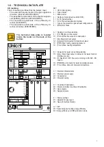
Page 43: ...put 10 Pcond Effective output in condensation 11 Qn Maximum heat output 12 Adjusted Qn Adjusted for rated heat output 13 PMS Max heating operating pressure 14 T max Max heating temperature B Domestic hot water circuit characteristics 15 Qnw Rated heat output in domestic hot water function if different to Qn 16 D Specific D H W flow rate according to EN 625 EN 13203 1 19 PMW Max domestic hot water ...

Page 44: ...the antifreeze function position the two knobs as shown in the figure This protection can intervene only if the electricity and gas supplies are connected If one of the two is not available and upon reset 11 SR a temperature of 2 C is detected the appliance will behave as described in tab pos 2 The heating system can be protected effectively from frost by using antifreeze products with inhibitor f...

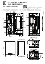
Page 45: ...URES AND DIMENSIONS NOTE Further details in the section Technical Information on the boiler page of the www unicalag it website 2 2 1 TECHNICAL FEATURES 2 2 VIEW WITH THE INDICATION OF THE MAIN COMPONENTS AND DIMENSIONS View from above View from below ...

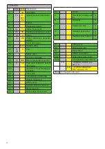
Page 46: ... TLC Flue gas collector safety thermostat 24 Aluminium Heat Exchanger Capacitor 25 Vent valve 26 Condensation drain trap 35 Ignition Trasformer 41 DHW sensor 42 DHW Expansion vessel 3 l 43 Water tank 60 l 44 DHW safety Valve 8 bar An Anode C Domestic hot water out let G G Gas inlet G F Cold water inlet G M Heating system flow G R Heating system return G Rc Filling valve Sb Drain water tank Sc Boil...

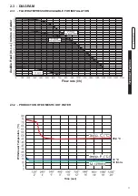
Page 47: ...s E N G L I S H 45 4 C 12 C 12 l min 2 3 DIAGRAM 2 3 1 FLOW RATE PRESSURE AVAILABLE FOR INSTALLATION Flow rate l h Avaible Head m c a metres of water 2 3 2 Production of Domestic Hot Water Time sec Withdrawal Temperature C ...

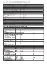
Page 48: ...ained with appliance operated with Nat Gas G20 2 4 1 DATA ACCORDING TO ErP DIRECTIVE Description Symbol Unit KON B 28 Nominal Heat Output Pnominale kW 27 Seasonal space heating energy efficiency ƞs 93 Seasonal efficiency class in heating mode A For CH only and combination boilers useful heat output Useful Heat Output in high tempera ture regime Tr 60 C Tm 80 C P4 kW 15 6 Useful efficiency at nom h...

Page 49: ... C D l min 18 4 Domestic hot water flow rate limiter l min 12 Production of D H W in continuous operation with t 45 K l min 9 Production of D H W in continuous operation with t 40 K l min 10 1 Production of D H W in continuous operation with t 35 K l min 11 5 Production of D H W in continuous operation with t 30 K l min 13 4 Production of D H W in continuous operation with t 25 K l min 16 1 Temper...

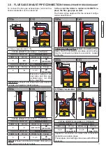
Page 50: ...here are aggressive corrosive vapours present in the installation room the appliance must be protected suitably and must be able to operate independently from the air in the room Attention Only mount the appliance on a closed wall made of non flammable materi al flat vertical so that the minimum distances required for installation and maintenance can be observed The boiler must be connected to a c...

Page 51: ...tc must be kept out of the reach of children as they are potential sources of danger Unical AG S p A will not be held liable for damage to persons animals or ob jects due to failure to comply with the instruction above As well as the appliance the packaging contains A DOCUMENTATION ENVELOPE User operating instructions booklet Instruction booklet for the installer and maintenance engineer 2 Spare p...

Page 52: ...ght The wall must not be made of flammable material Since the temperature of the wall on which the boiler is installed and the temperature of the coaxial exhaust pipe do not exceed in normal oper ating conditions a room temperature beyond 60 K it is not necessary to observe the minimum distances from flammable walls For boilers with double intake and exhaust pipes in the event of cross ing flammab...

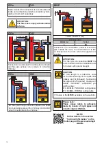
Page 53: ... min 250 mm max 500 Horizontal exhaust and intake terminals directed outside via coaxial or double pipes C33x C33 TOTAL LENGTH LA intake L Exhaust COAXIAL Ø60 100 DOUBLE Ø80 FROM m TO m FROM m TO m 1 7 0 5 0 5 40 20A 20S COAXIAL Ø80 125 DOUBLE Ø60 FROM m TO m FROM m TO m 1 9 1 1 20 10A 10S ertical exhaust and intake terminals directed out side via coaxial or double pipes C53x C53 C53 NOT ALLOWED C...

Page 54: ...th counterlow in the chimney C63x C63 Boiler intended for connection to a combustion air intake and combustion products evacuation system approved and sold separately ATTENTION The flue must comply with standards in force ATTENTION For the type of connection B23P the room follows the same installation rules for boilers with natural draught Please note These values relate to exhausts made by means ...

Page 55: ...ave no contractual or extra contractual liability for damage caused due to incorrect installation and use and in any case failure to comply with the instructions provided by the manufacturer Adapter for double systems NOTE For further details relating to pres sure drops of the individual compo nents for information on standards rules and regulations for proper flue gas exhaust refer to the Technic...

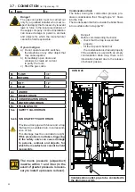
Page 56: ... carried out only by a qualified installer who must re spect and apply that foreseen by relevant laws in force in the local prescriptions of the supply company Incorrect installation can cause damage to persons animals and objects for which the manufacturer cannot be held responsible If you smell gas a Do not operate electric switches the telephone or any other object that may cause sparks b Immed...

Page 57: ...en the system connections have been completed the circuit can be filled This operation must be performed carefully respect ing the following phases open the radiator vent valves and make sure the automatic valve is working properly in the boiler open the filling tap gradually making sure that the automatic air release valves installed on the system work properly close the radiator air release valv...

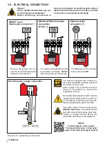
Page 58: ...OT after having removed the jumper MODULATING thermostat connection RT OT Remember that a bipolar switch must be installed on the boiler power line with over 3 mm between contacts easy to access making maintenance quick and safe The power cable must be replaced by UNICAL AG S p A authorised techni cal staff using original spare parts only Failure to comply with the above can jeopardise the safety ...

Page 59: ...as supply valve open has the system been checked for gas leaks is the outside main switch ON is the water tank safety valve efficient and is it connected to the drains is the condensation drain trap connected to the drains has the system been checked for water leaks are the ventilation conditions and minimum distances to perform any maintenance ensured have the GAS HEATING and DOMESTIC HOT WATER p...

Page 60: ... the calibration function is activated Release it when the SERVICE symbol appears Do not press it for more than 9 This function is not activated if there is a block or domestic hot water request 2 MAXIMUM OUTPUT By turning the knob B onto MAX the boiler will operate at maximum output 3 illuminated symbols 4 DISABLING The calibration function stays active for 15 minutes To disable the CALIBRATION f...

Page 61: ...ake and exhaust terminal check that there are no gas leaks 3 12 ADJUSTING THE BURNER 2 Minimum output adjustment Operate the boiler in calibration mode at MINI MUM OUTPUT see 3 11 1 Once the burner is on check that the CO2 MINI MUM value corresponds to that indicated in the table NOZZLES PRESSURE Correct it if needed by turning with a screwdriver the screw R CLOCKWISE to increase it ANTI CLOCKWISE...

Page 62: ... G31 5 3 27 5 6 28 37 1500 5800 9 8 8 10 7 10 7 0 34 kg h 2 17 kg h 60 Values are referred in CH mode Not included for Swiss market Check the levels of CO2 often especially with low flow rates They refer to the boiler with a closed combustion chamber NOZZLES PRESSURE FLOW RATES TABLE In some areas there may be particular distribution conditions of gas with a mixture that requires an opti misation ...

Page 63: ... mode by decreasing the burner output value 3 12 1 ADAPTATION OF THE POWER TO THE HEATING SYSTEM E g to decrease the output of the boiler to 24 kW edit parameter HP about 85 Act on parameter HP par 4 2 parameters that can be edited from control panel to achieve the value corresponding to the desired output The user is NOT authorised to activate the func tion described below ...

Page 64: ...d previously Vent and if necessary restore the heating pres sure until reaching a pressure of 0 8 1 0 bar Open the gas shut off valve Switch the boiler on Make sure the appliance is gas tight and water tight Remount the front casing of the appliance Failure to perform Inspections and Main tenance can entail material and personal damage TABLE OF RESISTANCE VALUES ACCORDING TO THE TEMPERATURE TO THE...

Page 65: ...ing Heat the TL until it intervenes at 95 C and check that it intervenes at 95 DK safety pressure switch against water deficiency 13 Does the pressure switch block the boiler if the water pressure is below 0 4 bar Without request close the shut off valves of the heating circuit open the drain valve to make the water pressure decrease Before pres surising again check the pressure of the expansion v...

Page 66: ... 20 C 30 10 C 20 0 C PUMP POST CIRCULATION VALUES FROM A DEFAULT 0 5 min 1 ALWAYS 0 5 min SELECTION Turn the HEATING knob B 2 OK NIGHT REDUCTION VALUES FROM TO TO DEFAULT 0 TA 0 5 TA 5 30 TA 30 0 TA 0 MAXIMUM HEATING OUTPUT VALUES FROM TO DEFAULT 0 Min 99 Max 99 PREHEATING VALUES FROM TO DEFAULT 0 1 0 EDITING THE VALUE Turn the DOMESTIC HOT WATER knob C The value flashes on the display CONFIRM SEL...

Page 67: ...e installing the appli ance For state of the art deaeration of the tank contact the LPG supplier or a person qualified in compliance with law If the tank has not been professionally deaerated ignition problems could arise In that case contact the supplier of the LPG tank To convert the boiler from one type of gas to another proceed as follows Disconnect the appliance from the elctrical power suppl...

Page 68: ...e protective screw and make sure there is no water leakage Attention After removing the protective screw a small amount of water could leak out Dry all wet surfaces before re assembling the casing 4 4 1 LEGIONELLA PROTECTION FUNCTION It is activated every 7 days 168 h if temperature of water contained into the tank has remained permanentemenet below 61 C throughout the legionella treatment period ...

Page 69: ...e switch E ACC RIL Ignition detection electrode MVD Diverter valve motor P Pump SR Flow heating sensor SRR Return heating sensor SS Domestic hot water probe Pred for R models TL Limit thermostat TLC Flue gas collector limit thermostat VG Gas valve VM Modulating fan SE External probe connection terminals TA1 OT Modulating TA connection terminals TA2 On off TA connection terminals ...

Page 70: ...place the external probe 14 1 RETURN PROBE Auxiliary SRR sensor inter rupted Check the wiring if needed re place the auxiliary sensor 22 30 2 SERVICE PARAMETERS Service parameters altered due to possible electromagnetic interferences Reset the altered parameters via the panel and or regola facile 21 3 POOR WATER CIRCULATION Poor circulation in primary circuit Check pump operation 12 and speed if t...

Page 71: ...ssure switch 16 10 EXCHANGER FREEZING 24 Exchanger freezing is detected If the heating sensor detects a temperature below 2 C burn er ignition is inhibited until the sensor detects a temperature above 5 C Disconnect the from the power supply close the gas valve defrost the exchanger carefully LIMIT THERM 11 SAFETY THERMOSTAT Intervention of the safety ther mostat 10 Press the unblock button on the...

Page 72: ...re was a pro blem solved of connection wiring 19 22 FLAME CONTROL Flame control damaged Replace the board INCONVENIENCES SOLUTIONS KON B 28 Flame noisy in cold ignition Act on parameter IG using the REGOLAFACILE section TECHNICAL MENU TSP parameters increasing the value by 5 10 max KON B 28 Flame noisy in steady state conditions increase the CO2 value max value for methane gas 9 6 min value 9 1 ma...

Page 73: ...37 ...

Page 74: ...38 ...

Page 75: ...39 ...

Page 76: ...enziali Unical declines every responsibility for the possible inaccuracies if owed to errors of transcript or press Also reserves the right to bring those changes that it will hold necessary to it own products or profits without jeopardizing its essential characteristics 46033 casteldario mantova italia tel 39 0376 57001 fax 39 0376 660556 info unical ag com export unical ag com www unical eu AG S...

Reviews: