11
Any solid residues that have been removed and any
parts that have been removed must be disposed of
in accordance with legislation in force.
When the maintenance operations are finished, the
initial connections must be set back up.
You must make sure that the appliance starts up
as required, ensuring that there is no return of the
combustion products during operation.
In case of any irregularities, make sure:
- the air inlets are working correctly
- that the chimney draught is correct
- that the difference in pressure between installation
room and outdoor environment is greater than 4
Pa.
At the end of the check and/or maintenance
operations, the professionally qualified technical
staff will issue an intervention report to the user,
indicating:
- any parts that have been replaced or installed
- any remarks, strong advice and requirements
The user must keep the report safe together with
the documents supplied with the appliance so that
it is available for future consultation.
Maintenance by BTA (Biomass Technical Assistance)
When commissioning the stove, the room
must be well ventilated as unpleasant
smells could develop during the first
hours of operation due to fumes coming
from paint and grease in the tube and
shell.
ATTENTION!
If flue gas temperature reaches 220°C during
standard operation of the stove (parameter
which can be modified by the technician), the
flue gas is modulated as follows:
• flue gas exhaust motor set at maximum
speed;
• pellet loading gearmotor at minimum speed;
• tangential heat exchange fan at maximum
speed.
This procedure lowers the temperature of the
flue gas. When it returns below the threshold
of 220°C, the stove restores the speed of the
three motors, bringing them back to the prior
setting.
In case of a power failure, when power is
restored, the display indicates the fault status
"Fire cool" (flame present). Suction will increase
to expel flue gas residue.
Images are purely indicative and may not correspond to the actual product.
They are to be intended as exemplifying to understand operation of the product.
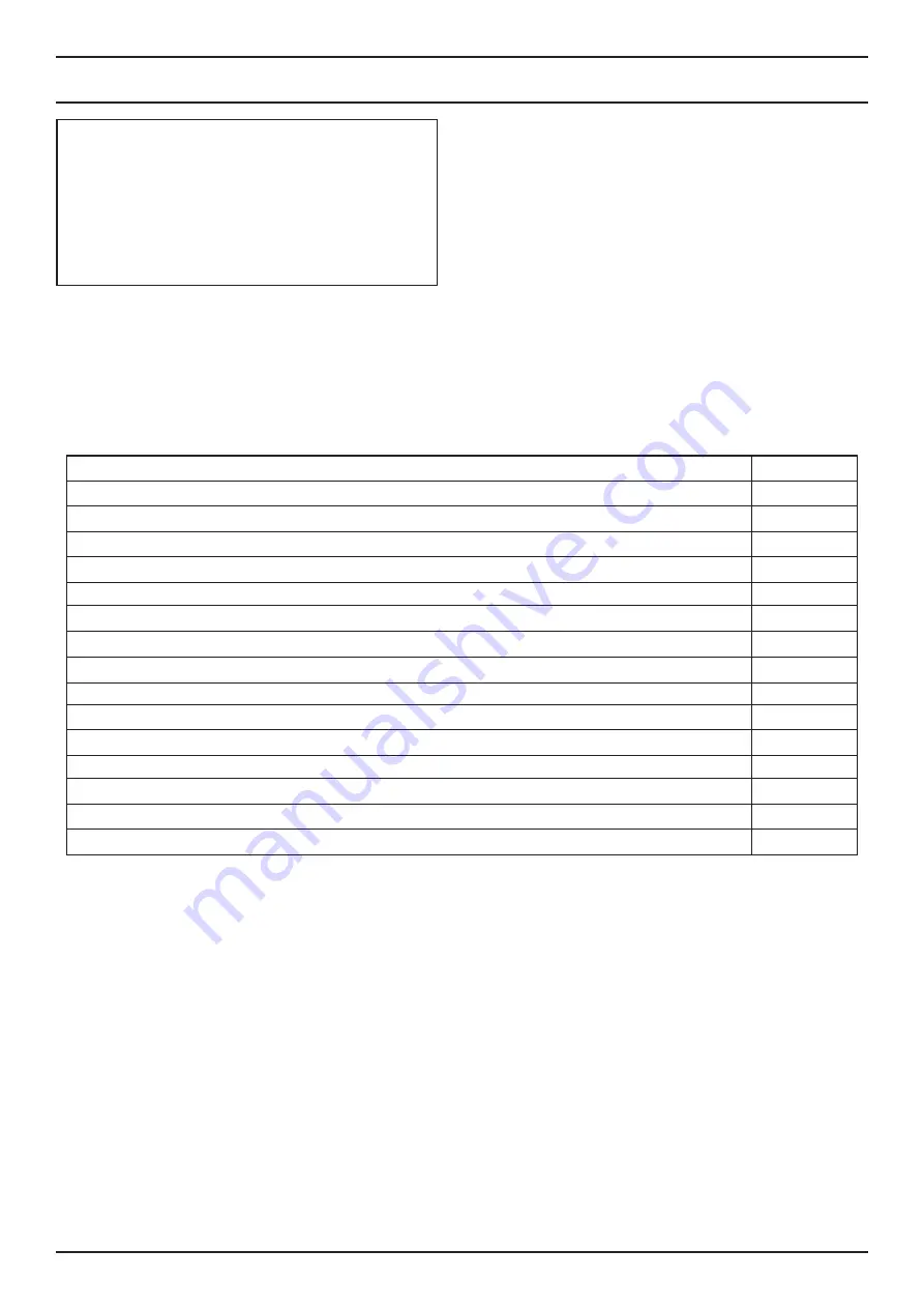
Maintenance operations
General internal and external cleaning
Thorough cleaning of exchange pipes
Thorough cleaning and descaling of crucible and relative compartment
Cleaning of motors, mechanical check of backlash and fixings
Cleaning of flue gas duct (repl. gaskets) and of the flue gas extraction fan compartment
Cleaning pressure switch
Probe check
Checking efficiency of remote control battery
Cleaning, inspecting and de-scaling the ignition resistance compartment,
replace it if required
Visual inspection of electric cables, connections and power cable
Cleaning pellet tank and checking screw-gearmotor assembly backlash
Checking sealing of door gaskets
Checking electric parts and electronic components
Functional inspection, screw feeding, ignition, operation for 10 minutes and extinction
Every year
X
X
X
X
X
X
X
X
X
X
X
X
X
X
X


