background image

8

Positioning

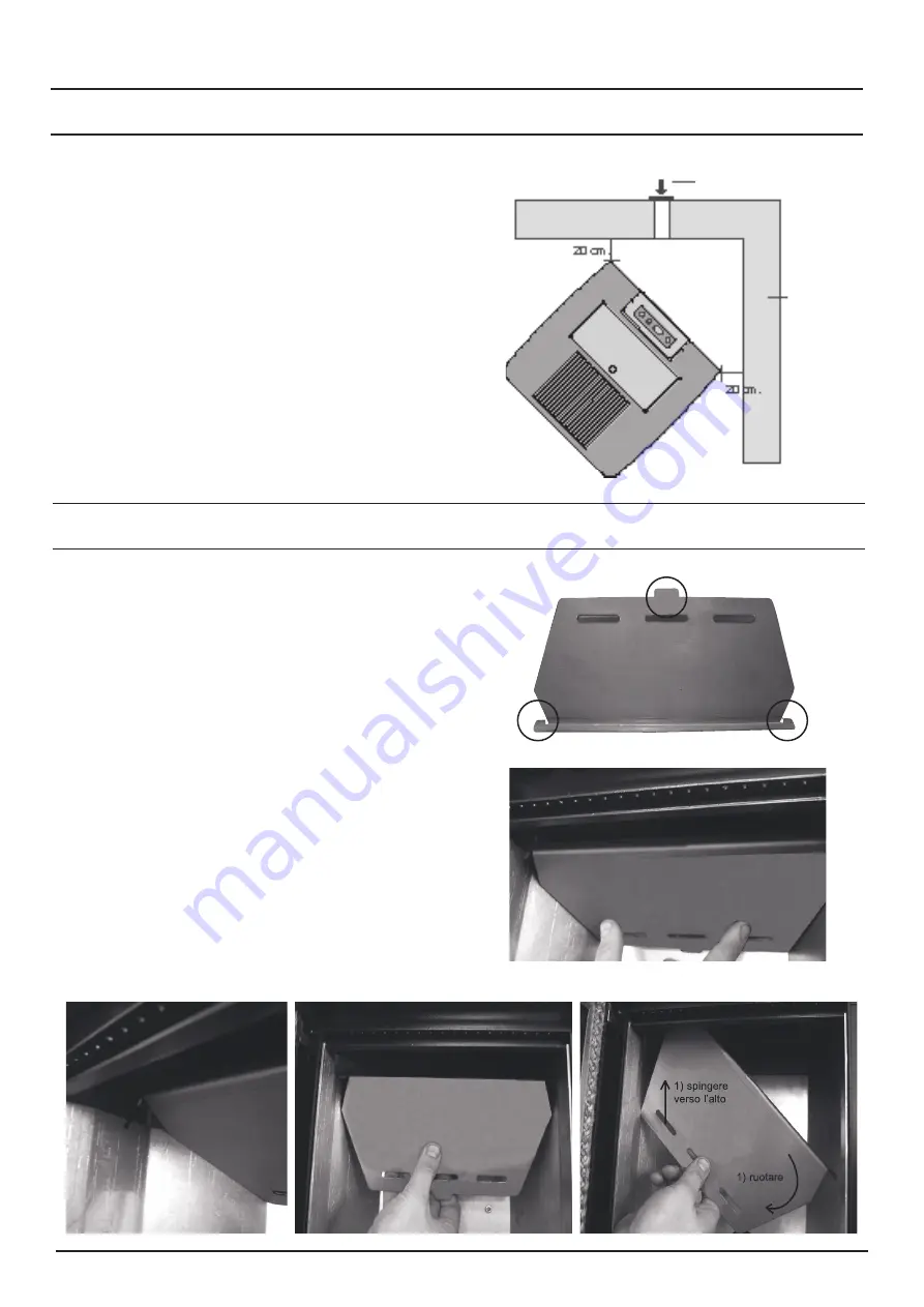
Minimum aeration for combustion air inlet

Certain measures and prescriptions must 

be respected to correctly and safely position 

the air inlet (Fig. 9.) They are distances to be 

respected to keep combustion air from being 

subtracted by another source: for example, 

opening a window can suck in outdoor air 

making it insufficient for the stove.

Make sure that the negative pressure measured 

between the installation room and outside is > 

4 Pa.

Fig. 9: distances from walls

Instructions to install the flame protection

Fig. 12: lifting 


the flame protection

Fig. 13: flame protection rotation

Fig. 14: removing the flame protection

Fig. 11: lifting the flame protection

Fig. 10: supporting hooks

combustion air 

intake (> 120 cm

2

)

wall

Remove  the  flame  protection  from  its  seat 

following the instructions provided in the 

following figures (Fig. 11-12-13-14). 

Use a vacuum cleaner to remove all the 

ashes deposited on the upper part. Once 

these operations are complete, mount the 

flame  protection,  making  sure  that  the  three 

supporting hooks are placed inside their seats 

correctly. 

Summary of Contents for .it 10.5

Page 1: ...it INSTALLATION AND MAINTENANCE INSTRUCTIONS 7 8 5 10 5...

Page 2: ...ntre Continuing to use the appliance in these conditions can cause fires or electrocutions If the supplementary air vent is not used only for ducted models check that the fan speed is at zero deactiva...

Page 3: ...intenance Failure to comply with the instructions in the manuals Use which does not comply with safety directives Installation which does not comply with standards in force in the country Installation...

Page 4: ...f the roof or in contact with the outside for example for open lofts must be covered with bricks and in any case well insulated Be built in such a way so that rain snow or foreign objects do not enter...

Page 5: ...guarantee regular combustion and proper environmental well being Make sure that the room where the stove is installed is sufficiently aerated The outdoor air inlet must communicate with the stove and...

Page 6: ...exhaust pipe Pellet tank capacity Autonomy Rated electric absorption at ignition Weight Dimensions LxWxH it 7 kW kW kg h mm Litres kg h W kg mm 6 97 2 84 6 42 2 64 1 4 0 6 92 70 92 06 80 20 13 22 9 1...

Page 7: ...connected to an earthed socket if the supplied cable is not long enough to reach the closest socket use a suitable extension cord Safety distances for fire protection The stove must be installed whil...

Page 8: ...d outside is 4 Pa Fig 9 distances from walls Instructions to install the flame protection Fig 12 lifting the flame protection Fig 13 flame protection rotation Fig 14 removing the flame protection Fig...

Page 9: ...riods of time the tank must be emptied from any residual fuel Parameter Diameter D Length L Water content M Ashes A 32 Mechanical durability DU Fine particles 3 15 mm Additives Lower Calorific Value Q...

Page 10: ...with that described in the standard UNI EN 14961 2 Press the ignition switch at the back of the stove the display will read OFF Ignition Press the key for 2 seconds After a few seconds the flue gas ex...

Page 11: ...ified by the technician the flue gas is modulated as follows flue gas exhaust motor set at maximum speed pellet loading gearmotor at minimum speed tangential heat exchange fan at maximum speed This pr...

Page 12: ...s It reserves the right to modify its products as deemed necessary or useful without jeopardising their essential features 46033 casteldario mantova Italy tel 39 0376 57001 telefax 39 0376 660556 info...

Reviews: