11
2
INSTALLATION
already fitted.
In addition to the a. m. panel board, packaged
in its own carton, in the combustion chamber,
as accessories, there are also:
- a carton containing the flanges for flow,
return and safety connections (if applicable)
with relevant gaskets and bolts, the
cylindrical brush for the cleaning of the
smoke pipes.
- cleaning brush handle extension.
- turbulators extractor.
- ceramic fiber rope for the insulation between
the door and burner blast tube.
- the turbulator cores, only for models ELL
170÷ELL 870 (for their positioning, see table
on page 33).
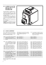
2.2 - HANDLING
The boiler can be moved into position by lifting,
through the upper hooks(s), or by the use of
rollers placed under the strong L profiles of
the basement.
If it necessary, due to the dimensions of the
boiler, it is possible to remove the front door
and the smoke chamber to facilitate the
introduction in the boiler house.
2.3 - POSITIONING IN THE
BOILER HOUSE
The installation of the boiler must be in
accordance with the relevant requirements of
the Gas Safety Regulations, current I.E.E.
Regulations, local water authority bye-laws and
it should also comply with any relevant
requirements of the local gas supplier, local
authority and the relevant Standard Codes of
Practice and building regulations.
The boiler house must be ventilated through
permanent openings having a total surface not
lower than 1/30
th
of the floor area of the boiler
house, with a minimum of 0.5 m
2..
Ventilation by grilles communicating directly
with the outside air is required at both, high
and low levels.
Do not obstruct the grates of aspiration of the
air or dissipation of the heat.
The boiler must be positioned so that there is
enough space available for the following:
- Access around the boiler fore servicing
- Space to open the boiler front door
- Space to access the burner.
The installation of the boiler as close as
possible to the chimeney position is highly
recommended.
To allow the cleaning of the smoke pipes, in
front of the boiler a clearance equal to the length
of the boiler, has to be available.
With the boiler door opened at 90°, the distance
between the front of the door and the adjacent
wall must be equal, at least, at the length of
the burner.
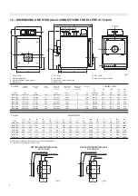
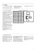
The boiler must stand on a non-combustible
floor (i.e. concrete or brick), of dimensions
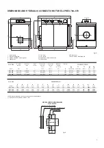
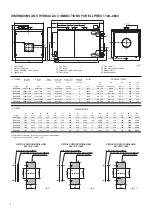
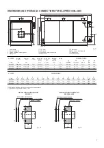
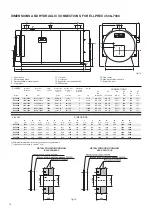
Q
x
R
(see dimensions table) which must be flat,
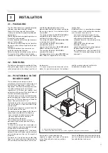
x = Not shorter than the boiler body
xx = Sufficient to allow accessibility to all the regulation, safety and control devices.
fig. 16
2.1 - PACKAGING
The ELLPREX boilers are supplied complete
with door and smoke chamber already
fitted, whilst the casing with the insulation
matress are contained in separate cardboard
packaging(s).
After having removed every packing make sure
the content is undamaged.
In case of doubt do not use the boiler and revert
your self to the supplier.
The elements of the packing must not be left to
the course of the children as potential sources
of danger.
The panel board and the accessories are
inside the combustion chamber.
Before starting the installation make sure that
the length and the width of the boiler body
received correspond to the dimensions
M, Q
and
R
of the ordered boiler, shown in the
previous tables and that the cartons, containing
the casing, or part of it, are marked with the
same model.
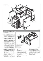
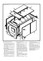
The casing of the boilers
ELL 170
to
ELL 510
,
complete with the insulation matress, is
contained in just one carton.
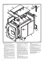
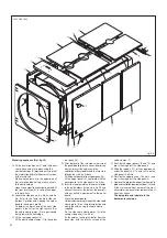
The casing of the boilers
ELL 630
to
ELL 2200
is contained in 3 cartons.
The casing of the boilers
ELL 2650
is
contained in 4 cartons.
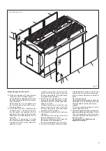
The casing of the boilers
ELL 3000
ed
ELL
3500
is contained in 3 cartons.
The casing of the boilers
ELL 4000
is
contained in 4 cartons.
The boilers between the model
ELL 4500
and
ELL 7000
, are supplied with the casing
level and of a suitable load bearing
capacity to support the weight of the boiler
(when filled with water) and any ancillary
equipment.
Once the installation has been made the boiler
must result perfectly horizontal and well stable
(to avoid vibrations and noise).
Summary of Contents for ELLPREX Series
Page 1: ...26739 01 13 rev 4 ELLPREX INSTALLATION USE AND SERVICING INSTRUCTION to be kept by the user...
Page 37: ...37 Notes...
Page 38: ...38 Notes...
Page 39: ...39 Notes...


