- 11 -
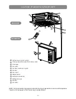
3. OUTLINE OF INDOOR & OUTDOOR UNITS
NOTE: The Figure has the only purpose to show the User how to operate for a correct use of the appliance.
Therefore, the real aspect of the Product may be lightly different.
1
2
3
4
5
6
7
8
9
10
11
12
Airflow louver (at air outlet)
Drain pump (drain water from Indoor Unit)
Drain pipe
Air outlet
Air filter (inside air-in grill)
Air inlet
Air-in grill
Display panel
IR Remote Controller
Refrigerant pipe
Air inlet
Air outlet
INDOOR UNIT
OUTDOOR UNIT
3
10
11
11
12
1
5
7
8
2
4
6
9
MOD
E
FAN
TEM
P
SLE
EP F
RES
H
LED
FOL
LOW
ME
TURB
O
SELF
CLEAN
ON/O
FF
ECO
TIM
ER
ON
TIM
ER
OFF
Summary of Contents for CMCS 12HI
Page 1: ...CMCS 12HI CMCS 18HI User Manual ...
Page 25: ...NOTES ...
Page 26: ...NOTES ...
Page 27: ...NOTES ...
Page 28: ...00335962 02 2016 ...


