Unibor CMD40 Original Instructions Manual Download Page 3

Unibor COMMANDO 40 

             Original Instructions 

         Nov 2019 


1) INTENDED USE


The intended use of this magnetic drill is to drill holes in ferrous metals. The magnet is used to hold the drill in place 
whilst the drill is functioning. It is designed for use in fabrication, construction, railways, petrochemical and any other 
applications when drilling ferrous metal. Any deviation from its intended use will not be covered by warranty.  


2) GENERAL SAFETY RULES


WARNING! 

When using electric tools basic safety precautions should always be followed to reduce the risk of fire, 

electric shock and personal injury, including the following. Please read these instructions before attempting to operate 
the machine. 
 
1.


Remove the power supply before carrying out any adjustment, servicing or maintenance. 

2.


Keep work area clear - cluttered areas and benches invite injuries. 

3.


Consider work area environment. 


Do not expose tools to rain. 


Do not use tools in damp or wet locations. 


Keep work area well lit (500 Lux recommended). 


Do not use tools in the presence of flammable liquids or gases. 


Ensure there is adequate space to gain access to the plug, mains and motor on/off switches.  

4.


Guard against electric shock: 


Avoid body contact with earthed or ground surfaces (e.g. pipes, radiators, cookers and refrigerators). 
Electric safety can be further improved by using a high-sensitivity (30 m A/0.1s) residual current device 
(RCD). 

5.


Keep other persons away. Do not let untrained persons, especially children, touch the tool or the extension cord 
and keep them away from the work area. 

6.


Store idle tools when not in use. All tools should be stored in a dry locked-up place, out of reach of children. 

7.


Do not apply too much force through the machine. It will do a better and safer job at the feeds for which it was 
designed. 

8.


Use the right tool. 


Do not force small tools to do the job of a heavy-duty tool. 


Do not use this tool for purposes not intended: e.g. do not use the magnetic drill to cut tree logs. 

9.


Dress properly. 


Do not wear loose clothing or jewellery; they can be caught in moving parts. 


Non-skid footwear is recommended when working outdoors. 


Wear a protective hair covering to contain long hair. This will reduce the risk of entanglement. 

10.


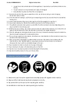
Use protective equipment when using this machine. 


Use safety glasses to prevent debris from damaging eyes. 


Use ear defenders or ear plugs for hearing protection. 


Use face or dust masks if cutting operations create dust. 


Use protective gloves to prevent swarf or debris cutting the skin.  

11.


When using the drill, always ensure a safe operating distance from any swarf and do not reach into the cutting 
area, or near the cutter, when the machine is running.  

12.


Connect dust extraction and collecting equipment, if devices are provided, ensuring these are properly connected 
and used. 

13.


Do not abuse the cord; never pull the cord to disconnect it from the socket. Keep the cord away from heat, oil and 
sharp edges. 

14.  Secure work where possible, use clamps or a vice to hold the work. It is safer than using your hand. 
15.


Do not overreach! Keep proper footing and balance at all times. 

16.


Maintain tools with care. 


Keep cutting tools sharp and clean for better and safer performance. 


Regularly check the machine for any wear or damage. 


Ensure the machine is clean and free from debris prior to use.  


Remove from the mains prior to any maintenance.  


Follow instructions for lubricating and changing accessories. 

Summary of Contents for CMD40

Page 1: ...40 Magnetic drilling machine Model Number CMD40 This machine Serial Number is CSA approved Unibor 77 Eisenhower Lane S Lombard IL 60148 Tel 6304959940 Fax 314 9685040 Email usa unibor com Website www uniborusa com ...

Page 2: ...edies for hole making 8 10 Wiring diagram 9 11 Exploded view of machine 10 12 Exploded view of gearbox and motor 13 13 Pipe adaptor kit 15 14 Fitting chuck 16 15 Maintenance 16 16 Trouble shooting 18 17 Cutter selection 19 18 Warranty statement 20 P N List of Contents with Magnetic Dill Unit Check list Y N RD4329 Safety Strap RD4088 Hexagon Spanner 4mm RD4152 Hexagon Spanner 3mm RD33154 Drill Chuc...

Page 3: ...ored in a dry locked up place out of reach of children 7 Do not apply too much force through the machine It will do a better and safer job at the feeds for which it was designed 8 Use the right tool Do not force small tools to do the job of a heavy duty tool Do not use this tool for purposes not intended e g do not use the magnetic drill to cut tree logs 9 Dress properly Do not wear loose clothing...

Page 4: ...nfluence of alcohol or any illegal substances 23 Check for damaged or missing parts before use of the tool it should be carefully checked to determine that it will operate properly for its intended function 24 The use of any accessory or attachment other than ones recommended in this instruction manual may present a risk of personal injury 25 Have your machine repaired by a qualified Unibor techni...

Page 5: ...D40 Maximum hand arm vibration magnitude measured at handle during operation in accordance with ISO5349 using a 15 16 dia cutter through a mild steel plate Vibration emission value a W 2 892 m s Uncertainty K 1 5m s Average noise level during cutting at operator s ear position LpA 88 4 dB A LwA 101 4 dB A uncertainty K 3dB A Ear and eye defenders must be worn when operating this machine Wear glove...

Page 6: ...ount of coolant is used and that care is taken to ensure that coolant does not enter the motor unit Cutting tools may shatter always position the guard over the cutter before activating the machine Failure to do so may result in personal injury On completion of the cut a slug will be ejected When not in use always store the machine in a safe and secure location Always ensure that approved Unibor a...

Page 7: ...mmended that the following extension lengths shall not be exceeded For 120v supply 11 ft of 3 core x 16AWG ALWAYS DISCONNECT THE MACHINE FROM THE POWER SOURCE BEFORE CHANGING CUTTERS 8 MOUNTING OF CUTTERS The machine has been made to accept cutters having 3 4 dia Weldon shanks The following procedure is to be used when mounting cutters Lay the machine on its side with feed handles uppermost ensuri...

Page 8: ...parts Replace part or parts Adjust where necessary 3 Excessive drilling pressure required Incorrectly re sharpened worn or chipped cutter Coming down on swarf lying on surface of workpiece Gib strips out of adjustment or lack of lubrication Swarf accumulated packed inside cutter Re sharpen or replace Take care not to start a cut on swarf Adjust setscrews and lubricate Clear cutter 4 Excessive cutt...

Page 9: ...Unibor COMMANDO 40 Original Instructions Nov 2019 9 10 WIRING DIAGRAM ...

Page 10: ...Unibor COMMANDO 40 Original Instructions Nov 2019 10 11 EXPLODED VIEW OF MACHINE MACHINE ...

Page 11: ...120V 230V 1 15 RD4078 M8 Flat Washer 2 16 RD4079 M8 Elastic Washer 2 17 RD43619 M8 88 Hex Head Tap Bolt 2 18 RD33632 Housing Assembly 1 19 RD4312 M6 12 Lock Screw 4 20 RD45622 Pin 3 8 2 21 RD4313 Sleeve 2 22 RD3303 Pinion Shaft Sleeve 1 23 RD4096 M6 Elastic Washer 5 24 RD4098 M6 20 Socket Cap Screw 5 25 RD4077 M4 6 Cross Panhead Screw 4 26 RD33250 Warning Label 1 27 RD4325 M5 16 Socket Cap Screw 2...

Page 12: ...33642 Capstan Arm 3 49 RD43091 Capstan Ball 3 50 RD33249 Brand plate 1 51 RD45621 M4 22 Cross Panhead Screw 1 52 RD4069 M4 External Tooth Washer 1 53 RD45604 Earth Tag 1 54 RD4070 M4 Flat Washer 2 55 RD4068 M4 Hexagon Nut 2 56 RD33341 Flat Key 1 57 RD4095 M6 Flat Washer 4 58 RD45606 Protecting Switch 1 59 RD43117 Cable Gland 1 60 RD43093 M4 14 Cross Panhead Screw 2 61 RD33145 Depth Gauge 1 62 RD33...

Page 13: ...Unibor COMMANDO 40 Original Instructions Nov 2019 13 12 EXPLODED VIEW OF MOTOR AND GEARBOX ...

Page 14: ... 3 8 2 RD33607 Gear Shaft 1 8 21 RD33608 Small Gear 1 8 22 RD33609 Inner Gear plate 1 8 23 RD45614 Bearing Pin 1 8 24 RD45522 Ball Bearing 6001 1 8 25 RD33610 RD33623 Armature 120V 230V 1 8 26 RD43603 Ball Bearing 629 1 8 27 RD35639 Inductor 1 8 28 RD33611 Fan Baffle 1 8 29 RD43625 Tapping Screw St4 8 60 2 8 3 RD33633 RD33631 Field Coil 230V 120V 1 8 31 RDB3069 Bearing Sleeve 1 8 32 RD33275 Motor ...

Page 15: ...ing care that the magnet is in line with the longitudinal axis of the pipe Switch on the magnet and move the sliding plates down to the outside diameter of the pipe Tighten the screws on both sides by hand then check once again that the full length of the moving plates is touching the pipe at the front and back fasten the plate securely Feed the safety strap through the lugs at the front of the ho...

Page 16: ...e work be certain that the power supply is disconnected Description Every operation 1 week 1 Month Visual check of machine for damage X Operation of machine X Check brush wear X Check magnetic base X Check alignment of the machine X Check grease X Check armature X Visually check the machine for damage The machine must be checked before operation for any signs of damage that will affect the operati...

Page 17: ...the movement and make any further necessary adjustments Try to ensure that all the screws are exerting a uniform pressure on the slide from top to bottom A perfectly adjusted slide will operate freely up and down without any sideways movement 5 Now raise the slide to its highest position Slightly undo the arbor bearing bracket and using fingers only tighten the screws 6 Place the machine on a stee...

Page 18: ...ottom of the armature worn out Gear s worn out No grease in gear box Motor humming big sparks and motor has no force Armature damaged Field burned Carbon brushes worn out Motor does not start or fails Damaged or defective wiring Damage to armature or field coil Damaged or defective brushes Guiding takes a great deal of effort Guide is set too tight Guide is dry Guide gear rack rotation system is d...

Page 19: ... Possible speed selection for mild steel with ideal conditions at 30 M min Speed selector position Cutter diameter Nominal RPM 1 1 1 2 270 2 1 330 3 15 16 400 4 470 5 5 8 570 6 9 16 610 This data is presented for guidance only and should be adjusted to suit site and material condition ...

Page 20: ...e operating conditions overload or insufficient servicing or maintenance 3 Defects caused by using accessories components or spare parts other than original Unibor parts 4 Tools to which changes or additions have been made 5 Electrical components are subject to manufacturer s warranty The warranty claim must be logged within the warranty period This requires the submission or sending of the comple...

Reviews: