background image

Steps

5 / 6

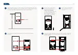
1

Paste the installation sticker on the wall, and keep the horizontal line parallel with the ground 
and the red line 1.4m distance to the ground; drill screw holes on suitable position on the wall 
according to the installation method (if use 86-box, then no need to drill holes).

3

2

Connect power cable, network cable and other wires, thread the connected tail line 
out the hole.

5

Insert the device upper slot into the hook on support, and align the lower slot with the 
limit slice, use hexagonal wrench to tighten the tamper screw in shown direction, to 

Move the support to align the holes 
on it with that on the wall, and use 

(Attention: If the wall has hard 
foundation, self-tapping screws shall 
be used together with expansion 
pipe; if the wall has soft foundation, 
use self-tapping screws directly.)

4

Align the socket of tail line with the 
interface at device back, use thr 

1.4m calibration line

1.4M

Outlet hole

1.4m calibration line

2

3

1

1.4m calibration line

1.4m calibration line

Summary of Contents for Uface 7 Pro

Page 1: ...PRODUCT BOOKLET Uface 7 Pro OS M375C4 V R23WFCQ ...

Page 2: ...r All parts of this booklet are reserved by our company including words pictures and graphics Without written permission no unit or individual shall extract copy translate or edit the content in this instruction Unit mm The software carried by the product is LAN version supports the secondary development Please mark the need for software version when place the order Please contact the customer ser...

Page 3: ...vice shall not be installed in shown black shadow area instead shall be installed in place with little sunlight impact no side light and no backlight Glass window can be deemed as no walls Sunlight shines indoor If the room has glass wall there is no shield for sunlight then it is suggested to hang curtains over the window and install the the recognition Glass window can be deemed as no walls Glas...

Page 4: ... the device upper slot into the hook on support and align the lower slot with the limit slice use hexagonal wrench to tighten the tamper screw in shown direction to Move the support to align the holes on it with that on the wall and use Attention If the wall has hard foundation self tapping screws shall be used together with expansion pipe if the wall has soft foundation use self tapping screws di...

Page 5: ...switch of magnetic door Wiring schematic drawing for sensor switch of automatic door Auto door controller assembly units Relay interface Sensor inside DC12V Ethernet Host Power access control Door exit inside Magnetic lock Host Relay interface Ethernet PUSH GND 12V COM NC NO 12V GND NO NC COM 12V 12V Power access control Door exit Magnetic lock Ethernet Host Power Relay Opening signal PUSH Public ...

Page 6: ...than 400KB 1 million pieces of recognition records 0 45KB and about 100 thousand pieces of on site capture images b Device using LAN support storing 50 thousand pieces of face images each image by 100KB and 1 million pieces of recognition records including the latest 10 thousand pieces of on site capture images Recognition speed less than 1s Support the interface connection in HTTP supports 232 se...

Page 7: ... This equipment generates uses and can radiate radio frequency energy and if not installed and used in accordance with the instructions may cause harmful interference to radio communications However there is no guarantee that interference will not occur in a particular installation If this equipment does cause harmful interference to radio or television reception which can be determined by turning...

Reviews: