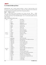
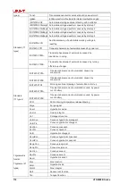
background image


104                                                                          UTG2000B Series 

(period of pulse train) will be hidden in parameter list. The range of burst period (period of pulse 
train) is 1µs~500s; the default “burst period” is 1ms.To change it, you can 
use multi-functional knob and direction key or press soft key Param 

  Period  after selecting 

type of pulse train as N cycle. 

  Burst period (period of pulse train) 

  waveform period 

×

recurring number (number of 

pulse trains). The waveform period is reciprocal of waveform frequency mentioned in “select pulse 
train”. 

  If burst period (period of pulse train) is too short, signal generator will automatically increase 

the period to allow output of a designated number of cycles. 

3.3.6 Counting of Burst 

In N cycle mode, counting of pulse train is used to designate the number of waveform cycles. It is in 
the range of 1~1000000 periods and 1 by default. To change it, you can use multi-functional knob 
and direction or press soft function key Param 

  Cycles  after selecting type of pulse train as “N 

cycle”. 

  Recurring number

  burst period 

×

  waveform frequency 

  If recurring number exceeds the above limit, signal generator will automatically increase period 

of pulse train to adapt to the designated counting of pulse train (without changing waveform 
frequency). 

3.3.7 Select Trigger Source 

The signal generator generates output of pulse train upon receiving a trigger signal, and then waits 
for the next trigger signal. The trigger source of pulse train can be internal, external or manual. To 
change it, you can use multi-functional knob and direction key on 
the interface for selecting type of pulse train or press soft key Param 

  Source . 

1)  In case of internal trigger, pulse train is output continuously with designated frequency. The 
frequency of pulse train output is determined by period of pulse train. The signal generator can 
output “N cycle” or “infinite” pulse train. 
2)  In case of external trigger, waveform generator will accept a hardware trigger that has been 
applied to external digital modulation interface (FSK Trig connector)of back panel. The waveform 
generator will output a pulse train upon receiving a TTL pulse with designated polarity. The signal 
generator can output “N cycle”, “gating” or “infinite” pulse train. 
3)  In case of manual trigger, backlight of Trigger on front panel flashes. A pulse train is output 
upon pressing Trigger. The signal generator can output “N cycle” or “infinite” pulse train. 

3.3.8 Trigger Output 

In case of internal or manual trigger source, the trigger signal (square wave) can be output through 
sync output interface. The signal is compatible with TTL level. 
Default status of trigger output: off; if you need to change press    Param 

  TrigOut  

  On   

  Inner trigger: the instrument outputs a square wave with 50% duty ration from the beginning of 

pulse train. The period equals to that of specified pulse train. 

Summary of Contents for UTG2122B

Page 1: ...User Manual UTG2000B Series Function Arbitrary Waveform Generator 2011 09 UNI T Technologies Inc...

Page 2: ......

Page 3: ...ni Trend device In order to use this instrument safely and correctly please read this manual thoroughly especially the Safety Notes part After reading this manual it is recommended to keep the manual...

Page 4: ...refers to the individual or entity that is declared in the guarantee In order to obtain the warranty service customer must inform the defects within the applicable warranty period to UNI T and to per...

Page 5: ...olation of this guarantee UNI T is responsible for the repair or replacement of defective products is the only remedy available to customers Regardless of whether UNI T and its distributors are inform...

Page 6: ...of 30MHz 25MHz 25MHz minimum margin time can reach to 11ns and its rising falling and duty ratio time are adjustable Pulse waveform of 30MHz 25MHz 25MHz adjustable time of rising falling and duty rati...

Page 7: ...Set output frequency 12 2 4 2 Set output amplitude 13 2 4 3 Set DC offset voltage 13 2 4 4 Set square wave 14 2 4 5 Set pulse wave 14 2 4 6 Set DC offset voltage 15 2 4 7 Set ramp wave 15 2 4 8 Set n...

Page 8: ...st 99 3 3 2 Type of Burst 101 3 3 3 Gating mode 102 3 3 4 Phase of Burst 103 3 3 5 Period of Burst 103 3 3 6 Counting of Burst 104 3 3 7 Select Trigger Source 104 3 3 8 Trigger Output 104 3 3 9 Trigge...

Page 9: ...n the product Alternating Current Ground Terminal for Testing Ground Terminal for Chassis On Off Button High Voltage Caution Protective Ground Terminal CE marking CSA International Spectrum Management...

Page 10: ...nd prevent damaging the product only trained personnel can perform the maintenance program To avoid fire or electric shock please notice rated operating range and product marks Do not use the product...

Page 11: ...distributor the distributor will arrange for repair or replacement 2 1 2 Check Accessories Power cord 1PCS USB data cable 1PCS BNC cable 1 meter 1PCS BNC red and black alligator clip connection cable...

Page 12: ...is shown in figure 2 1 1 USB port 2 ON OFF 3 Display Screen 4 Main Menu Button 5 Secondary Menu Button 6 Utility and setting 7 Number buttons 8 Manual trigger 9 Sync output terminal 10 Functional kno...

Page 13: ...protection is valid 2 3 2 Rear Panel The rear panel is shown in figure 2 2 1 External analog modulation input connector 2 External digital modulation frequency meter connector 3 LAN port 4 USB port 5...

Page 14: ...labels use button to flip over 1 Labels on the right of screen Highlighted display indicates that the label is selected If not press corresponding soft key to select 2 Labels at the bottom of screen...

Page 15: ...d dBm 2 Press number button to input 300 3 Press unit mVpp 2 4 3 Set DC offset voltage Default waveform sine wave with 0V DC offset voltage with 50 termination Steps for setting DC offset voltage to 1...

Page 16: ...ired numerical value and select the unit 2 4 5 Set pulse wave Example period 2ms amplitude 1 5Vpp offset 0V duty 25 rising time 200us and falling time 200us 1 Press Menu Wave Type Pulse Param and then...

Page 17: ...ing DC offset voltage to 3V 1 Press Menu Wave Type DC If the current DC voltage is valid adapt the same DC voltage value 2 Enter 3 3 Select required unit V Note This parameter can be set by multifunct...

Page 18: ...nd DC offset 0mV Steps for setting Quasi Gauss noise with 300mVpp amplitude and 1V DC offset Press Menu Wave Type Noise Param to enter parameter editing mode After setting enter number and unit 2 4 9...

Page 19: ...ermutation of which can represent the output waveform Basic expression Vout f x for example f x x 1 x x 1 the interface is as below The output from the signal source is duplicate signal within limited...

Page 20: ...symbol or expression For example input x 1 x x 1 the interface is as below The default initial value is 0 end value is 180 and expression is sin x The unit can be in rad or The setup procedures are a...

Page 21: ...output CH1 CH2 OFF Load 50 high resistance 1 to 1k Channel merge ON OFF When this function is ON channel 1 merges with channel 2 Channel duplicate Channel can be duplicated each other in settings sta...

Page 22: ...nnel merge The signal source of CH1 CH2 will output CH1 CH2 waveform normally When you turn on the channel merge function it will output CH1 CH2 waveform Select Channel merge select ON OFF the interfa...

Page 23: ...cy ratio amplitude deviation ratio or phase deviation ratio of these two channels The parameters of them are the reference for each other When you change the parameter of one channel the parameter of...

Page 24: ...b net mask Gateway MAC address Select Utility Network to enter into network setting Note Since there are numerous items in Utility there are 2 pages you need to press again to skip to next page 1 Acce...

Page 25: ...ystem Language English simplified Chinese traditional Chinese Clock Internal external Clock output ON OFF Sound ON OFF Separator Comma space null Backlight 10 30 50 70 90 Load You can select factory s...

Page 26: ...irst instrument clock output ON to 10MHz In of the second instrument clock source is external set both instruments with the same output frequency For more instrument synchronization just connect the o...

Page 27: ...ick Confirm d It takes 2 to 3 minutes to upgrade During this process the device will restart to validate the upgrade Note Do not power off during upgrade process 12 Help Help system provides the help...

Page 28: ...modulation wave The modulation of CH1 and CH2 is independent you can set up the same or different mode for them Press Menu Mod Type AM to enable the AM function Then the modulated waveform will be dis...

Page 29: ...wave 1 Hz 120MHz 1 Hz 80MHz 1 Hz 60MHz Square wave 1 Hz 30MHz 1 Hz 25MHz 1 Hz 25MHz Ramp wave 1 Hz 5MHz 1 Hz 4MHz 1 Hz 3MHz Impulse wave 1 Hz 30MHz 1 Hz 25MHz 1 Hz 25MHz Arbitrary wave 1 Hz 25MHz 1 Hz...

Page 30: ...xternal waveform The range of external signal frequency is 0Hz 20 kHz Set Modulation Depth Modulation depth indicates the extent of amplitude variation which is expressed as percentage Settable range...

Page 31: ...n Signal Parameter After enabling the AM function press Param soft key and the interface will appear as following Press corresponding soft key then enter required numerical value and select the unit S...

Page 32: ...Square in turn to select square wave as carrier wave signal Press Param soft key again and the interface will pop up as following Press corresponding soft key then enter required numerical value and...

Page 33: ...enter number 80 and press soft key with number keyboard for setting modulation depth Enable Channel Output Press CH1 button start channel 1 output quickly Or enable output by pressing Utility and then...

Page 34: ...In frequency modulation modulated waveform is usually composed of carrier wave and modulation wave Carrier wave frequency will change as the amplitude of modulation wave changes Press Menu Mod Type FM...

Page 35: ...ve arbitrary wave except DC and noise the default is sine wave After selecting FM modulation press Carrier soft key to enter carrier waveform selection interface Carrier Wave Waveform FM wave waveform...

Page 36: ...wave falling ramp wave arbitrary wave and noise After enabling FM function the default of modulation wave is sine wave If need to change press Param ModWave in turn Square wave duty ratio is 50 Lead...

Page 37: ...Frequency deviation represents the difference between frequency of the FM modulated waveform and the carrier frequency Settable range of FM frequency deviation is from 1 Hz to the maximum of current c...

Page 38: ...es Set Modulation Signal Parameter Press Param soft key Then the interface will show as following Press corresponding soft key then enter required numerical value and select the unit Set Carrier Wave...

Page 39: ...e Sine in turn to select sine wave as carrier wave signal Press Param soft key and the interface will pop up as following Press corresponding soft key first then enter required numerical value and sel...

Page 40: ...then enter number 5 and press kHz soft key with number keyboard for setting frequency deviation Press CH1 button start channel 1 output quickly Or enable output by pressing Utility and then CH1 Setti...

Page 41: ...se modulation modulated waveform is usually composed of carrier wave and modulation wave The modulation of CH1 and CH2 is independent you can set up the same or different mode for them Press Menu Mod...

Page 42: ...ft key to select carrier waveform Carrier Wave Frequency Setting If you need to set up the carrier wave frequency see Carrier Wave Frequency Setting Modulation Source Selection This device can select...

Page 43: ...deviation Modulation wave Frequency Setting When modulation source is internal frequency of modulation wave can be modulated After enabling PM function the default of modulation wave frequency is 100H...

Page 44: ...unction Press Menu Mod Type PM in turn to start the PM function Set Modulation Signal Parameter Press Param soft key and the interface will show as following Press corresponding soft key first then en...

Page 45: ...gnal Parameter Press Carrier Type Sine in turn to select sine wave as carrier wave signal Press Param soft key and the interface will pop up as following Press corresponding soft key then enter requir...

Page 46: ...Phase Deviation Press Return soft key to back to the following interface for setting phase modulation Press Param PhaseDev soft key then enter number 200 and press soft key with number keyboard for s...

Page 47: ...utput by pressing Utility and then CH1 Setting After channel output is opened backlight of CH1 button is on and on the right side of channel information label the font OFF changes to PM meaning open c...

Page 48: ...nt logic of modulation signal ASK Modulation Selection Press Menu Mod Type ASK in turn to start the ASK function the device will output modulated waveform with ASK rate and carrier wave set currently...

Page 49: ...FSK Trig connector For example output the carrier wave amplitude of current setting when external input logic is low and output currently set carrier wave amplitude when input logic is high output amp...

Page 50: ...s Set Carrier Wave Signal Parameter Press Carrier Type Sine in turn Press Param soft key and the interface will pop up as following Press corresponding soft key then enter required numerical value and...

Page 51: ...setting carrier wave parameter press Return soft key to go back to the following interface for setting phase modulation Press Param Rate soft key again then enter number 300 and press Hz soft key with...

Page 52: ...tput by pressing Utility and then CH1 Setting After channel output is opened backlight of CH1 button is on and on the right side of channel information label the font OFF changes to ASK meaning open c...

Page 53: ...ation Selection Press Menu Mod Type FSK in turn to start the FSK function The device will output modulated waveform with current setting Carrier Wave Waveform Selection Press Carrier soft key to enter...

Page 54: ...lation source is internal internal modulation wave is a square of 50 duty ratio not adjustable The FSK rate can be set to customize the moving frequency between carrier wave frequency and hop frequenc...

Page 55: ...lt rate is 100Hz If need to change press Param Rate in turn Please refer to Carrier Wave Frequency to set up the frequency Comprehensive Example Firstly make the instrument work in frequency shift key...

Page 56: ...key again and the interface will pop up as following Press corresponding soft key first then enter required numerical value and select the unit Set Hop Frequency and FSK Rate Press Return soft key to...

Page 57: ...the interface will pop up as following Press corresponding soft key first then enter required numerical value and select the unit Enable Channel Output Press CH1 button start channel 1 output quickly...

Page 58: ...Phase Shift Keying PSK In phase shift keying DDS function generator can be configured to move between two preset phase carrier wave phase and modulation phase Output carrier wave signal phase or hop...

Page 59: ...y to enter carrier waveform selection interface Carrier Wave Frequency Setting See Carrier Wave Frequency Setting Modulation Source Selection UTG2000B function arbitrary waveform generator can select...

Page 60: ...et After enabling PSK function PSK rate can be set and the settable range is 2mHz to 1MHz the default rate is 100Hz If need to change press Param Rate in turn Modulation Phase Setting Modulation phase...

Page 61: ...gnal Parameter Press Carrier Type Sine in turn to select sine wave as carrier wave signal Press Param soft key and the interface will pop up as following Press corresponding soft key then enter requir...

Page 62: ...and Modulation Phase Press Return soft key to go back to the following interface Press Param soft key and the interface will pop up as following Press corresponding soft key then enter required numer...

Page 63: ...tput by pressing Utility and then CH1 Setting After channel output is opened backlight of CH1 button is on and on the right side of channel information label the font OFF changes to PSK meaning open c...

Page 64: ...different modulation mode for channel 1 and 2 Select BPSK modulation Press Menu Mod Type BPSK successively to use BPSK function if Type is not highlighted press soft key Type to select After BPSK func...

Page 65: ...he frequency between carrier phase and modulation phase can be set After you use BPSK function you can set BPSK rate which is in the range of 2mHz 1MHz and 100Hz by default You can change it with mult...

Page 66: ...o be 1kHz and PN code to be PN15 The specific steps are as follows Use BPSK function Press s Menu Type BPSK successively press soft key Type to select if Type is not highlighted to use BPSK function S...

Page 67: ...put the value and then select the unit Set BPSK rate modulation phase and PN code Press Return to return to the interface below after setting carrier parameters To set some parameter press correspondi...

Page 68: ...pressing Utility and then CH1 Setting After channel output is opened backlight of CH1 button is on and on the right side of channel information label the font OFF changes to BPSK meaning open channel...

Page 69: ...or different modulation mode for channel 1 and 2 Select QPSK modulation Press Menu Mod Type QPSK to enable QPSK function if Type is not highlighted press soft key Type to select After QPSK function i...

Page 70: ...erent modulation mode for channel 1 and 2 Select OSK modulation Press Menu Mod Type OSK to use BPSK function if Type is not highlighted press soft key Type to select After OSK function is used UTG2000...

Page 71: ...input logic is low carrier phase is output when external input logic is high modulation phase is output Set vibrate time Press the soft key and enter the period value Range 8ns 200ns default is 1ms Se...

Page 72: ...this example You can set with multi functional knob and direction key You can also press corresponding soft keys of function again when the interface below will pop up To set some parameter press corr...

Page 73: ...e parameter press corresponding soft key input the required value and select the unit Figure 3 2 Set modulation rate 4 Use channel output Press CH1 button start channel 1 output quickly Or enable outp...

Page 74: ...e sum of product of carrier amplitude and modulation factor and product of amplitude of modulation wave and modulation factor The modulation mode of the two channels is mutually independent You can co...

Page 75: ...nal modulation source After you use SUM function you can see that modulation source is internal by default You can change it with multi functional knob on the interface for using SUM function or by pr...

Page 76: ...sing amplitude modulation function or by pressing Param ModFreq The range of modulation frequency is 2mHz 1MHz In case of external modulation source modulation wave and frequency will be hidden in par...

Page 77: ...dulation parameter 3 Set FSK rate and modulation phase After setting up press Return to turn to the interface below 4 Use channel output Press CH1 button start channel 1 output quickly Or enable outpu...

Page 78: ...enable output by pressing Utility and then CH1 Setting After channel output is opened backlight of CH1 button is on and on the right side of channel information label the font OFF changes to SUM meani...

Page 79: ...f basic waveform setting to quickly set corresponding carrier waveform Set carrier frequency See Carrier wave frequency setting Select modulation source UTG2000B function arbitrary waveform generator...

Page 80: ...l be used to modulate carrier waveform DSBAM depth is controlled by 5V signal level on external analog modulation input terminal Modulation In connector of back panel For example if modulation depth i...

Page 81: ...elect if Type is not highlighted 2 Set carrier waveform parameters Press Param Type Sine if TYPE is not highlighted press TYPE You can use the multifunctional knob and soft keys to set the parameters...

Page 82: ...80 UTG2000B Series Input the number and select the unit 3 Set DSBAM rate and modulation phase After setting up press Return to turn to the interface below...

Page 83: ...1 12 Quadrature Amplitude Modulation QAM In QAM two signals of the same frequency but with phase difference of 90 normally indicated by Sin or Cos are used as carrier wave which is subject to amplitu...

Page 84: ...tion Set carrier signal parameters QAM carrier waveform is sine wave Figure 3 13 Select carrier waveform Set carrier frequency See Carrier wave frequency setting Set modulation mode Modulation mode is...

Page 85: ...modulation mode to be 64QAM default source is PN7 The specific steps are as follows 1 QAM function Press Mod Type QAM successively press soft key Type to select if Type is not highlighted to use QAM f...

Page 86: ...y pressing Utility and then CH1 Setting After channel output is opened backlight of CH1 button is on and on the right side of channel information label the font OFF changes to QAM meaning open channel...

Page 87: ...for channel 1 and 2 Select PWM Press Menu Mod Type PMW successively to use PWM function if Type is not highlighted it may be necessary to press soft key Type twice to display the next screen of sub t...

Page 88: ...ob and direction key in the interface or press soft function key Param Duty input the required value and select the unit Select modulation source UTG2000B function arbitrary waveform generator can sel...

Page 89: ...PWM function default of modulation wave frequency is 100Hz Press Param ModFreq to change Modulation frequency range 2mHz 1MHz When modulation source is external parameter list will hide the modulation...

Page 90: ...ft keys of function on the above interface for using PWM function when the interface below will pop up To set some parameter press corresponding soft key input the required value and select the unit F...

Page 91: ...responding soft keys of function again when the interface below will pop up To set some parameter press corresponding soft key input the required value and select the unit Figure 3 26 Set rising edge...

Page 92: ...numeric keyboard and press soft key to set duty ratio deviation Figure 3 28 Set duty ratio deviation 5 Enable channel output Press CH1 button start channel 1 output quickly Or enable output by pressin...

Page 93: ...to stop frequency in designated frequency sweep time Trigger source can be internal external or manual it can generate frequency sweep output for sine wave square wave ramp wave and arbitrary wave exc...

Page 94: ...quency sweep waveform 3 2 2 Set Starting and Stop Frequency Starting frequency and stop frequency are upper limit and lower limit of frequency sweep Function arbitrary waveform generator always sweeps...

Page 95: ...stop frequency can vary with frequency sweep waveform See the table below for the frequency range of frequency sweep wave Table 3 4 Carrier waveform Frequency UTG2122B UTG2082B UTG2062B Min Max Min M...

Page 96: ...unction key Param SweepTime input number through numeric keyboard and press corresponding soft key of unit Figure 3 36 Set frequency sweep time 3 2 5 Select Trigger Source The signal generator generat...

Page 97: ...ill be hidden in parameter list as trigger output is also achieved through external digital modulation interface FSK Trig connector This interface cannot be simultaneously used as external trigger inp...

Page 98: ...igital modulation interface FSK Trig connector is used as input When it is used as input i e internal trigger source rising edge means that rising edge of external signal triggers output of a frequenc...

Page 99: ...ou can set amplitude with multi functional knob and direction key You can also press corresponding soft function keys again when the interface below will pop up To set some parameter press correspondi...

Page 100: ...To set some parameter press Param input the required value and select the unit Figure 3 43 Set trigger frequency 4 Enable channel output Press CH1 button start channel 1 output quickly Or enable outp...

Page 101: ...rain including N cycle gating and infinite It can generate pulse train for sine wave square wave ramp wave pulse wave arbitrary wave except DC and noise only applicable to gating pulse train The modul...

Page 102: ...ect frequency sweep waveform The interface that pops up is shown in the figure below Figure 3 47 Select waveform 3 Set waveform frequency In N cycle and gating modes waveform frequency defines signal...

Page 103: ...Press soft keys Type N Cyc successively on the interface for starting pulse function to enter N cycle mode In this mode the waveform generator will output a waveform with designated recurring number p...

Page 104: ...orm when gated signal is spurious output will be immediately stopped Polarity can be changed with multi functional knob and direction key on the interface for selecting gating mode as shown in the fig...

Page 105: ...or sine wave square wave ramp wave and pulse wave 0 is the point at which the waveform passes 0V or DC offset value in forward direction For arbitrary waveform 0 is the first waveform point downloaded...

Page 106: ...pulse train upon receiving a trigger signal and then waits for the next trigger signal The trigger source of pulse train can be internal external or manual To change it you can use multi functional kn...

Page 107: ...ive polarity means that external signal triggers output of a pulse train at low level When it is used as output i e internal or manual trigger and trigger output is ON the default edge is rising edge...

Page 108: ...Hz They are reciprocal i e T 1 f You can also press soft function key Param Freq Freq again press the soft key Freq twice for conversion between frequency and period in parameter list when the interfa...

Page 109: ...some parameter press corresponding soft key input the required value and select the unit Figure 3 56 Set period of pulse train Enable channel output Press CH1 button start channel 1 output quickly Or...

Page 110: ...e storage See Table 3 4 list of built in arbitrary wave for the name of waveform The instrument creates and edits arbitrary waveform through upper computer software and reads arbitrary waveform data f...

Page 111: ...eform points one by one with this frequency Point by point output mode can prevent loss of important waveform point The default is No In such case arbitrary waveform is output with fixed length 8 192...

Page 112: ...wave Ramp Ramp wave NegRamp Negative ramp wave PPulse Positive pulse NPulse Negative pulse Noise Noise wave Sinc Sinc function Cardiac Electrocardiography EEG Electroencephalogram DualTone Dual tone...

Page 113: ...omial Laplace Laplace distribution Legend Quintic Legendre polynomial Log Denary logarithmic function LogNormal Logarithmic normal distribution Lorentz Lorentzian function Maxwell Maxwell distribution...

Page 114: ...up changer Standard 17 types ISO7637 2 TP3A Transient phenomena of automobile caused by conversion ISO7637 2 TP3B Transient phenomena of automobile caused by conversion ISO7637 2 TP4 Working sectiona...

Page 115: ...Tan Arctan function ATanH Arc hyperbolic tangent function Window function Window 17 types Bartlett Bartlett window BarthannWin Corrected Bartlett window Blackman Blackman window BlackmanH BlackmanH wi...

Page 116: ...rbitrary Waveform UTG2000B creates and edits complicated arbitrary waveform of any amplitude and shape through powerful upper computer software Please see Operation Manual of UTG2000B Arbitrary Wavefo...

Page 117: ...on front panel is connected well 4 Restart the instrument 5 If the product still cannot be used normally please contact with the dealer or local office and let us serve you 4 2 No Waveform Output Set...

Page 118: ...s proven to be defective during warranty period UNI T will repair and replace according to provisions of warranty To arrange repair or ask for the whole warranty please contact with the nearest sales...

Page 119: ...ing edge of pulse wave 1 s Falling edge of pulse wave 1 s Arbitrary wave Built in arbitrary wave Acos Play mode No AM modulation Modulation source Internal Modulation wave Sine wave Modulation frequen...

Page 120: ...hase 2 180 Phase 3 270 Phase 4 270 OSK modulation Modulation source Internal Oscillation time 1ms OSK rate 100Hz DSBSM modulation Modulation source Internal Modulation wave Sine modulation rate 100Hz...

Page 121: ...ng number 1 Gated polarity Positive polarity Trigger source Internal Trigger output Off Trigger edge Rising edge System parameter IP type DHCP Clock source Internal Clock output Off Sound of buzzer On...

Page 122: ...pical value test condition output frequency 0dBm DC 1MHz 60dBc 1MHz 10MHz 55dBc 10MHz 40MHz 50dBc 40MHz 80MHz 45dBc 80MHz 120MHz 40dBc THD typical value 0 2 DC 20kHz 1Vpp Spurious signal anharmonic te...

Page 123: ...mum rising falling time typical value 5ns 6ns 7ns Shake 150ps play mode Nonvolatile storage 160 waves Output amplitude 20MHz 1mVpp 10Vpp 50 60MHz 1mVpp 5Vpp 50 120MHz 1mVpp 2Vpp 50 20MHz 2mVpp 20Vpp h...

Page 124: ...ernal Modulation wave Square wave Duty ratio 50 Modulation frequency 2mHz 1MHz FSK Carrier wave Sine wave square wave 1 Hz 30MHz ramp wave arbitrary wave Source Internal external Modulation wave Squar...

Page 125: ...e square wave ramp wave arbitrary wave Type Linear or logarithmic Frequency sweep time 1ms 500s 0 1 Trigger source Manual external or internal Burst Waveform Sine wave square wave ramp wave pulse nois...

Page 126: ...frequency 100mHz 200MHz Accuracy 51ppm Frequency resolution 6 digit s coupled mode DC general technical specifications Display LCD 4 3 inches TFT resolution 480 272 Power supply Power supply 100 240 V...

Page 127: ...TG2000B dual channel Standard configuration A power line up to local standard A USB data line One BNC cables 1 m One BNC red and black alligator clip connection 1 m A CD for users A product warranty c...

Page 128: ...n the instrument frequently in the light of use Cut off the power and then clean with soft cloth that is wet but not dripping wipe floating dust off the exterior of instrument with mild detergent or c...

Page 129: ...UTG2000B Series 127 This user manual may be revised without prior notice...

Page 130: ...128 UTG2000B Series...

Reviews: