background image

49

UTD4000 Four-channel User Manual

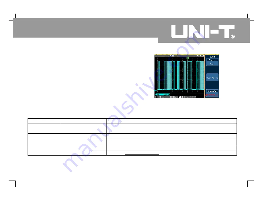
Adjusting the Holdoff Time

Yo u c a n a d j u s t t h e h o l d o f f t i m e t o o b s e r v e
complicated waveforms (e.g. pulse string series).
Holdoff time means the waiting time for the trigger
c i r c u i t t o b e r e a d y f o r u s e a g a i n w h e n t h e
oscilloscope is restarted. During this time the
oscilloscope will not trigger until the holdoff is
complete. For example, if you wish to trigger one
group of pulse series at the first pulse, set the holdoff
time to the pulse string width as shown in Figure 2-18.

Table 2-1

Trigger holdoff menu

7

Figure 2-18 Use the holdoff function to synchronize

complicated signals

Function Menu

Setup

Explanatory Note

Window

Press [

] to switch between the Main

and

Extended

F1

.

Dual Xbase

Enter the dual time base menu. See Table 2-9

----

Holdoff

Use the

control knob to adjust holdoff time

MULTIPURPOSE

.

96.0000ns~ 1.50000s

Summary of Contents for UTD4000 Series

Page 1: ...uch the ground Before connecting the input or output terminal ensure the unit is properly grounded The probe ground cable is the same as ground potential Do not connect the ground cable to non ground voltage or high voltage To prevent fire and excessive current shock please check all rated values and label data Read the manual carefully and check the rated values before connecting the unit Do not ...

Page 2: ... following messages may appear on the product means potential damage that is immediate means potential damage that is not immediate means possible damage to this product or other properties The following icons may appear on the product Safety Messages and Symbols Warning Warning statements identify conditions or practices that could result in injury or loss of life Caution Caution statements ident...

Page 3: ... storage oscilloscope series Example illustrations are provided to solve various testing problems Chapter 1 User Guide Chapter 2 Instrument Setups Chapter 3 Practical Illustrations Chapter 4 System Prompts and Trouble shooting Chapter 5 Servicing and Support Chapter 6 Appendixes Appendix A Technical Indicators Appendix B Accessories for UTD4000 Four channel Digital Storage Oscilloscopes Appendix C...

Page 4: ...tures They are your perfect tools to complete testing tasks swiftly and efficiently This manual is a user guide for 3 models of this digital storage oscilloscope series UTD4000 Four channel User Manual Model Bandwidth Single channel Sampling Rate Dual channel Sampling Rate Equivalent Sampling Rate UTD4104C UTD4204C 100MHz 200MHz 2GS s 2GS s UTD4304C 300MHz 2GS s 1GS s 1GS s 1GS s 50GS s 50GS s ...

Page 5: ...ng and measurement requirements 2GS s real time sampling rate and 50GS s equivalent sampling rate Dual time base function unrivaled waveform detail observation and analysis capabilities 24k storage depth 60M equivalent storage depth 1024k recording length Unique envelop sampling feature with direct visual display of carrier wave details after amplitude modulation Scroll display in scan mode for co...

Page 6: ... 4 x 1 2m 1 1 10 1 probe For details refer to the probe instructions These accessories conform with EN61010 031 2008 standards Power line conforming to international standards applicable in the country of use User Manual USB connecting cable UT D06 UTD4000 four channel oscilloscope communication control software USB device 2x multimeter test lead 2x c to voltage converter module UT M03 UT M04 AUTO...

Page 7: ...ystem Getting to Know the Horizontal System Getting to Know the Trigger System Chapter 2 Instrument Setups Setting the Vertical System Setting the Horizontal System Setting the Trigger System Setting the Display System User Guide General Inspection Setting the Sampling System Storage and Recall 1 6 6 10 11 11 13 15 17 18 35 40 52 56 59 UTD4000 Four channel User Manual ...

Page 8: ... Illustration 3 Acquiring single signals Illustration 4 Reducing random noise of signals Illustration 5 Using the cursors for measurement Illustration 6 Using the X Y function Illustration 7 Illustration 8 Utility Function Setup Cursor Measurement Multimeter Measurement Vedio signal triggering Using the dual time base function Illustration 9 Using the multimeter 64 70 74 76 77 78 78 80 80 81 83 84...

Page 9: ...r 5 Chapter 6 Technical Indicators Appendix A Technical indicators Appendix B Appendix C Maintenance and Cleaning Appendix D Upgrading System Software on USB Accessories for UTD4000 Four channel Digital Storage Oscilloscope Series Factory Setups 96 96 96 98 106 106 115 116 117 UTD4000 Four channel User Manual ...

Page 10: ...rself with the operation front panel This chapter briefly describes the operation and functions of the front panel so you can get started with your UTD4000 four channel digital storage oscilloscope as quickly as possible Your UTD4000 Four channel oscilloscope comes with a front panel with at a glance functions for easy operation There are knobs and function keys on the front panel The functions of...

Page 11: ...Figure 1 1 Series Digital Storage Oscilloscope UTD4000 Four channel 2 UTD4000 Four channel User Manual ...

Page 12: ...3 UTD4000 Four channel User Manual Figure 1 2 Back cover of UTD4000 four channel digital storage oscilloscope USB device communication interface External trigger channel ...

Page 13: ...SCALE SCALE SEC DIV UTD4304C 300MHz 2GS s DIGITAL STORAGE OSCILLOSCOPE POSITION POSITION POSITION POSITION POSITION UTD4000 Four channel User Manual Figure 1 3 Series Digital Storage Oscilloscopes Front Panel UTD4000 Four channel 4 Trigger controls Horizontal controls Frequently Used Menus Multifunction knob Vertical controls Probe compensation signal output Analog signal input USB Host interface ...

Page 14: ... interface Trigger status display Displaying the horizontal trigger position Trigger frequency counter Channel vertical attenuation range Trigger level Waveform display window The menu varies with individual function keys Channel vertical reference Displaying main time base setup ...

Page 15: ... any missing items against this list If any item is missing or damaged please contact your NI T dealer or our local office If the exterior of the unit is damaged or it is not operating normally or it fails to pass the performance test please contact your UNI T dealer or our local office In the event of any shipping damages please retain the packaging and notify our shipping department or your UNI ...

Page 16: ...asurement accuracy Press the button and twice then press the control knob to perform the function Press and then press to go to the next page There press then the control knob To recall default setup see Figure 1 5 At the end of the above process press to enter the CH1 menu MULTIPURPOSE MULTIPURPOSE Utility key Power switch Figure 1 5 Warning To avoid danger ensure the digital storage oscilloscope...

Page 17: ...cess signals in the following steps Connect the probe of the digital storage oscilloscope to the CH input terminal and set the attenuation switch of the probe to X Figure 1 10 1 7 Figure 1 6 Four channel input and external trigger channel 8 EXT external trigger channel Figure 1 7 Setting the attenuation switch of the oscilloscope probe UTD4000 Four channel User Manual ...

Page 18: ...H1 CH2 10 Connect the probe tip and ground clamp to the connection terminal for the probe compensation signal Press and you will see a square wave in the display 1kHz approximately 3V peak to peak value in a few seconds as shown in Figure 1 Press twice to close CH1 then press to activate CH2 and repeat steps 2 and 3 Use the same method for CH3 and CH4 9 Figure 1 8 Setting the deflection factor of ...

Page 19: ... connector and the ground clamp to the ground cable connector of the probe compensator Activate CH1 then press 3 If you see an Undercompensation or Overcompensation waveform display adjust the adjustable capacitance tab of the probe with a screwdriver with non metal handle until a Correct Compensation waveform shown in the above figure is displayed AUTO 2 Observe the displayed waveform Overcompens...

Page 20: ... is larger than 1 1 Connect the signal to be tested to the signal input channel 2 P r e s s T h e o s c i l l o s c o p e w i l l automatically set the vertical graticule factor scanning time base and trigger mode Should you require to make more detailed check you can adjust manually after the auto setup process until you get the optimal waveform display As shown in the figure below there are a gr...

Page 21: ...N CH1 CH2 CH3 CH4 REF MATH VOLTS DIV REF MATH GROUND 2 Change the vertical setup and observe changes of status information You can identify changes of any vertical range by reading the status display column at the lower corner of the waveform window Turn the vertical knob to change the vertical range You will find that the range in the current status column has changed accordingly Press or and the...

Page 22: ...expanded you can adjust graticule of the window there 1 Use the horizontal knob to change the horizontal time base setup and check any changes in status information Turn the horizontal knob to change the time base range You will find that the time base range in the current status column has changed accordingly Range of horizontal scanning rate is 5ns div 50s div UTD4104C in steps of 1 2 5 POSITION...

Page 23: ...UTD4000 Four channel User Manual 14 Shortcut key for resetting the trigger point to horizontal zero When the trigger point has shifted significantly away from the horizontal centre point use the POSITION knob to quickly reset the trigger point to the horizontal centre point You can also use the horizontal knob for adjustments POSITION Definition Trigger point Holdoff means the actual trigger point...

Page 24: ...int of the trigger signal press the trigger knob To display trigger menu contents 1 Use the trigger knob to change the trigger level You will see a trigger sign on the screen that indicates the trigger level The sign will move up and down with the knob While you move the trigger level you will find the trigger level value on the screen changing accordingly 2 Open the trigger key see the figure 1 t...

Page 25: ...E SLOPE MULTIPURPOSE Notes UTD4000 Four channel User Manual 16 I c o n u t i l i t y f u n c t i o n o f t h e knob Press this key to quickly return to the centre point POSITION Icon utility function of the trigger knob Press this key to quickly return to horizontal ground level i e trigger zero level LEVEL I c o n u t i l i t y f u n c t i o n o f t h e knob Press this key to confirm selection MU...

Page 26: ...r t i c a l s y s t e m Setting up the horizontal system Setting up the Trigger system Setting up the sampling method Setting up the display mode Storage and recall Setting up the help system Automatic measurement Cursor measurement Auto setup run stop key Multimeter Multipurpose control knob It is recommended that you read this chapter carefully to understand the various measurement functions and...

Page 27: ...uantities of input signal Intercept DC quantities of the input signal Display reference ground level without disconnecting the input signal BW Limit Full 20MHz Full band width Limit bandwidth to 20MHz to reduce noise display VOLTS DIV Coarse Fine Coarse tune in steps of 1 2 5 to set up the vertical graticulefactor of the vertical system Fine tune means further tuning within the coarse tune setup r...

Page 28: ... of the signal being tested will be intercepted The waveform display is as follows Ω Ω Press twice to select DC 1M Both DC and AC quantities of the testing signal being inputted to CH1 can pass through The waveform display is as follows F1 19 UTD4000 Four channel User Manual Figure 2 1 DC quantities of the signal are intercepted AC coupling setup DC coupling setup Figure 2 2 Both DC and AC quantit...

Page 29: ...bandwidth limit CH1 F2 Take applying a signal to Ch1 as an example the signal to be tested contains high frequency quantities Press to turn CH1 on then press and F1 Bandwidth is now set to full bandwidth The signal being measured can pass through even if it contains high frequency quantities The waveform display is as follows Figure 2 3 Channel is set to ground mode Ground coupling setup Figure 2 ...

Page 30: ...when the probe attenuation factor is 10 1 set the probe attenuation factor at 10X in the channel menu Apply this principle to other values to ensure the voltage reading is correct The figure below shows the setup and vertical range display when the probe is set at 10 1 21 UTD4000 Four channel User Manual Figure 2 5 Waveform display when bandwidth limit is on Bandwidth limit 20MHz The BW bandwidth ...

Page 31: ... deflection factor in even smaller steps within the current vertical range so as to continuously adjust the vertical deflection factor within the range of 2mV div 5V div without interruption Waveform inversion The displayed signal is inverted 180 degrees Figure 2 8 shows the non inverted waveform Figure 2 9 shows the inverted waveform Figure 2 7 Coarse tuning and fine tuning the vertical Fine tune...

Page 32: ...CH1 CH2 CH3 and CH4 and the digitally filtered waveform The menu is as follows Operating Math Functions 23 UTD4000 Four channel User Manual Figure 2 9 Inversion setup for vertical channel inverted Inverted waveform Waveform inversion icon Figure Math functions 2 10 Math channel range ...

Page 33: ...1 as CH2 waveform Set 1 as CH3 waveform Set 1 as CH4 waveform Source Source Source Source Type Math To carry out functions Operator Source Source 2 Source 1 Source 2 Source 1 Source Source 1 Source 2 1 2 Source 2 CH1 CH2 CH3 CH4 Set 2 as CH1 waveform Set 2 as CH2 waveform Set 2 as CH3 waveform Set 2 as CH4 waveform Source Source Source Source Next page 2 2 Go to next page ...

Page 34: ...atory Note Compress 1 1 1 10 1 100 1 1000 Scale the waveform by ratio There are four ratios to choose from 1 1 1 10 1 100 1 1000 Y Offset Use the control knob to move the waveform vertically MULTIPURPOSE Y Level Use the control knob to adjust the vertical scale factor MULTIPURPOSE Pre 1 2 Return to previous page ...

Page 35: ... With FFT you can conveniently observe the following types of signals Measure the harmonic wave composition and distortion of the system Demonstrate the noise characteristics of the DC power Analyse oscillation Figure FFT Frequency 2 11 Fundamental frequency component 1 MHz Third harmonic frequency component 3MHz FFT vertical graticule unit mV horizontal graticule unit Hz div ...

Page 36: ... FFT algorithm functions Window Hamming Blackman Rectangle Hanning Set Hamming window function Set Blackman window function Set Rectangle window function Set Hanning window function Vertical coordinate Linear V dB Set the vertical coordinate unit to linear or V dB Next 2 2 Go to next page Function Menu Setup Explanatory Note Y Offset Use the control knob to move the waveform vertically MULTIPURPOS...

Page 37: ... finish resulting in transient interruption of high frequency at the connection point In frequency domain this is known as leakage To avoid leakage multiply the original waveform by one window function to set the value to 0 for start and finish compulsively For application of the window function please see the table below How to use FFT functions Signals with DC quantities or DC offset will cause ...

Page 38: ... noise Hamming Frequency recognition rate is marginally better than Hanning window Temporary or fast pulse Signal level varies greatly before and after Blackman The best amplitude recognition rate and the poorest frequency recognition rate Mainly for single frequency signals to search for higher order harmonic wave Definition FFT recognition rate Nyquist frequency means the quotient of the samplin...

Page 39: ...Digital filtering Function Menu Setup Explanatory Note Source CH1 CH2 CH3 CH4 Set CH1 as filter target Set CH2 as filter target Set CH3 as filter target Set CH4 as filter target Type Filter Digital filtering Filter Type Low pass High pass Band pass Set the filter to low pass filtering Set the filter to high pass filtering Set the filter to band pass filtering Next 2 2 Go to next page ...

Page 40: ... filtering Use the control knob to set the maximum frequency MULTIPURPOSE Lower Limit Effective only during high pass filtering or band pass filtering Use the control knob to set the minimum frequency MULTIPURPOSE Y Offset Use the control knob to move the waveform vertically MULTIPURPOSE Pre 1 2 Return to previous page Y Level Use the control knob to adjust the vertical graticule factor MULTIPURPO...

Page 41: ...press the control knob to confirm and the waveform originally stored in that position can be recalled For instructions on storing or recalling reference waveforms on the USB device read Storage and Recall 3 Press F1 for RefB to select the second signal source for the math function by repeating step 2 4 To close the reference waveform press In actual application when using your UTD4000 to measure a...

Page 42: ...one with the control knob Press the control knob to confirm MULTIPURPOSE To display the amplitude and time base contents of the current waveform Next 2 2 Go to next page Function Menu Setup Explanatory Note Y Offset Use the control knob to move the waveform vertically MULTIPURPOSE Y level Use the control knob to adjust the vertical graticule factor MULTIPURPOSE OFF Close the reference waveform Pre...

Page 43: ...haracter positions that need to be changed Use the control knob to change the selected characters or numerals Y Offset Y level OFF are operative only after the reference waveform has been recalled or imported Note 1 F4 Note 2 F1 F1 Note 3 REF MULTIPURPOSE MULTIPURPOSE Function Menu Setup Explanatory Note File name Use the control knob and F key to set the document name to be imported from the USB ...

Page 44: ... position Adjust the horizontal positions of channel waveforms including math waveforms Resolution of this control button changes with the time base Horizontal scaling Adjust the main time base i e SEC DIV When time base extension is on you can use the horizontal scaling knob to change the delay scanning time base and change the window width Two horizontal control knobs Use the knob to change hori...

Page 45: ... waveform Distance between the triggering position and the horizontal centre point The time base value of main time base M1 i e SEC DIV Horizontal parameter interface definitions Function Menu Setup Explanatory Note Window Press to switch between the main screen and expanded window F1 Dual Xbase Enter the dual time base menu See Table 2 9 Holdoff Use the control knob to adjust holdoff time MULTIPU...

Page 46: ...ncrease and decrease the selected zone in size by turning the horizontal knob The lower part is the horizontally expanded waveform Please note that the recognition rate of expanded time base relative to the main time base is now higher as shown in the above figure Since the waveform shown in the entire lower part corresponds to the selected zone in the upper part you can increase the extended time...

Page 47: ...fy the waveform times whereas in the dual time base mode you can magnify details of the waveform being observed by thousands of times In effect the main time base storage depth is increased by thousands of times The dual time base menu and its operation are as follows The Math function is disabled in the dual time base mode Note 100 Figure 2 15 Dual time base Delayed time base M2 Main time base M1...

Page 48: ...annel can be displayed in the dual time base mode Main Dual X Adjust When M1 is the main time base use the horizontal and knobs to adjust into main time base parameters When M2 is the main time base use the horizontal and knobs to adjust into main time base parameters POSITION SEC DIV POSITION SEC DIV M1 M2 CH1 CH2 CH3 CH4 BACK Return to the horizontal menu M2 Shift Set delayed time base M2 to mov...

Page 49: ... of your oscilloscope comprises a trigger knob and a trigger button Edge Pulse Video and Slope rate Trigger is set to occur when the signal is at the rising or falling edge You can use the trigger knob to change the trigger point s vertical position on the trigger edge i e the intersection point of the trigger level line and the signal edge on the screen When the pulse width of the trigger signal ...

Page 50: ... the external trigger source by 5 Set to AC power trigger CH1 and CH2 trigger their respective signals alternately CH3 and CH4 trigger their respective signals alternately Ch1 CH2 CH3 CH4 EXT EXT 5 LINE CH1 CH2 CH3 CH4 Mode The system automatically acquires waveform data when there is no trigger signal The scan baseline is shown on the display When the trigger signal is generated it automatically ...

Page 51: ...er at the signal s rising edge Set to trigger at the signal s falling edge Set to trigger at the signal s rising and falling edges Rise Fall Rise Fall Function Menu Setup Explanatory Note Type Pulse width Trigger Source Set CH1 CH2 CH3 or CH4 as the signal source trigger signal Set to external trigger or divide the external trigger source by 5 Set to AC power trigger CH1 and CH2 trigger their resp...

Page 52: ...al is generated trigger scan occurs One trigger will occur when there is an input trigger signal Then trigger will stop Auto Normal Single Pulse setup See Table 2 12 Set the pulse width Function Menu Setup Explanatory Note Type Pulse Polarity Set the positive pulse width as the trigger signal Set the negative pulse width as the trigger signal Positive Negative When Trigger occurs when pulse width ...

Page 53: ...width trigger to 20 0ns 10s with the control knob MULTIPURPOSE Back Return to the pulse width trigger menu Function Menu Setup Explanatory Note Type Video Source Set CH1 CH2 CH3 or CH4 as the signal source trigger signal Set to external trigger or divide the external trigger source by 5 Set to AC power trigger CH1 and CH2 trigger their respective signals alternately CH3 and CH4 trigger their respe...

Page 54: ...ory Note Standard PAL NTSC Suitable for PAL video signals Suitable for NTSC video signals Sync Set the video odd field to synchronized trigger Set the video even field to synchronized trigger Set the line signal to synchronize with trigger Set synchronized trigger on the specified line and adjust by turning the control knob lines for PAL lines for NTSC MULTIPURPOSE 625 525 Odd Field Even Field All...

Page 55: ...er Manual 46 Slope trigger If slope trigger is selected trigger occurs when the signal s rising or falling rate meets the set condition For the trigger menu see Table 2 15 below Figure 2 17 Video trigger Field synchronization ...

Page 56: ...l trigger source by 5 Set to AC power trigger CH1 and CH2 trigger their respective signals alternately CH3 and CH4 trigger their respective signals alternately Ch1 CH2 CH3 CH4 EXT EXT 5 LINE CH1 CH2 CH3 CH4 Mode The system automatically acquires waveform data when there is no trigger signal The scan baseline is shown on the display When the trigger signal is generated it automatically turns to tri...

Page 57: ...t the falling edge within the threshold for trigger Rise Fall Slew rate Set the slew rate value with the control knob MULTIPURPOSE Threshold Low High High Low Change the low level value with the control knob Change the high level value with the control knob Change the high and low level value with the control knob MULTIPURPOSE MULTIPURPOSE MULTIPURPOSE Back Return to the slew rate trigger menu Alt...

Page 58: ...ger until the holdoff is complete For example if you wish to trigger one group of pulse series at the first pulse set the holdoff time to the pulse string width as shown in Figure 2 18 Table 2 1 Trigger holdoff menu 7 Figure 2 18 Use the holdoff function to synchronize complicated signals Function Menu Setup Explanatory Note Window Press to switch between the Main and Extended F1 Dual Xbase Enter ...

Page 59: ... starting edge time of every data frame 1 The signal used for trigger The signal for trigger can be obtained from various sources input channel CH1 CH2 CH3 CH4 external trigger EXT EXT 5 and LINE etc The most common trigger source is to select one of the four input channels The channel selected as trigger source can operate normally whether the input waveform is displayed or not This trigger signa...

Page 60: ...be set to 50ms div or slower to generate a roll waveform In this mode your oscilloscope samples waveforms only when triggering conditions are met The system stops acquiring data and waits when there is no trigger signal When the trigger signal is generated trigger scan occurs In this mode you only have to press the RUN button once and the oscilloscope will wait for trigger One sampling will occur ...

Page 61: ...ion By observing pretrigger data you can see the waveform before trigger occurs For example you can detect the glitch that occurs when the circuitry starts Observation and analysis of trigger data can help you identify the cause of glitch As shown below button in the control zone is the function key for the sampling system Press the key to pop out the sampling setup menu You can use this menu to a...

Page 62: ...unction Menu Setup Explanatory Note Acquisition Ordinary sampling mode Peak detect mode Set to average sampling with display of the average number of times Envelop sampling Normal Peak Average Envelop Average number of times In the Average mode Set the average number of times in multiples of 2 i e 2 4 8 16 32 64 128 256 To change the average number of times use the control knob shown on the left i...

Page 63: ...e high frequency cyclical signals 3 To avoid mixed envelop when observing a signal select Peak Detect To reduce random noise of the displayed signal select average sampling and increase the average number of times in multiples of 2 i e selecting from 2 to 256 Figure 2 20 Waveform without average Figure 2 21 Waveform when 32 time ...

Page 64: ...vals to reconstruct waveform In this acquisition mode the oscilloscope identifies the biggest and smallest values of the input signals at each sampling interval and use these values to display the waveform In effect the oscilloscope can acquire and display narrow pulse which would otherwise be omitted in the sampling mode Noise seems to be more significant in this mode The oscilloscope acquires se...

Page 65: ...u to adjust the display mode DISPLAY DISPLAY 9 Figure 2 22 Function key for the sampling Function Menu Setup Explanatory Note Format Voltage relative to time horizontal graticule is displayed There are two groups in X Y display mode The first group is CH1 for X input and CH2 for Y input The second group is CH for X input and CH for Y input 3 4 YT XY Type Sampling points are linked for display Samp...

Page 66: ... normal rate Waveform on the screen is maintained for 1 second and then refreshed Waveform on the screen is maintained for 2 seconds and then refreshed Waveform on the screen is maintained for 5 seconds and then refreshed Waveform on the screen remains on display New data will be added continuously until this function is disabled Auto 1s 2s 5s Infinite Intensity In Fast ACQ mode intensity of the w...

Page 67: ...ith the CH1 or CH3 knob and move figures vertically with the CH2 or CH4 knob Adjust the dimension and shape of XY figures with of the four channels and turn the knob to improve the display quality of the lissajous figure Thanks to the unique display feature your oscilloscope can display channel waveform and lissajous figure concurrently The UTD4000 series also offers the following functions Automa...

Page 68: ...ects the capability to observe signal movements speedily As shown below the button in the control zone is the function key for the storage system Press the button to display the storage setup menu You can use this menu to save waveforms or setup status of the oscilloscope in the internal memory or the USB device and recall any stored waveform through RefA or RefB or press to recall the setup statu...

Page 69: ...waveforms can only be imported to the oscilloscope in REF mode and cannot be displayed on any other interface CSV waveforms can be opened in EXCEL on a PC It is a group of voltage and time correlation 2D data STORAGE Note 0 Function Menu Setup Explanatory Note Type Select a signal source waveform displayed on the screen Wave Source Select waveform from CH1 Select waveform from CH2 Select waveform ...

Page 70: ... see note MULTIPURPOSE F1 2 34 P Format See note CSV Iternal OK After confirming go back to the reference waveform storage menu If there is a USB drive it will be exported to the USB otherwise the prompt I O operation failed will appear Function Menu Setup Explanatory Note Type Save the current front panel setup status 1 10 Save To save on the internal memory of the oscilloscope select a save posi...

Page 71: ...will be exported to the USB otherwise the prompt I O failure will appear when exporting a waveform After confirming go back to the save setup menu If the document exists on the USB it will be imported otherwise the prompt I O will appear when importing a waveform operation failed Function Menu Setup Explanatory Note 1 10 Load Recall 10 internal save positions and select one of them with the contro...

Page 72: ...splay waveform to the USB device in bmp format Export Enter the USB menu See Table 2 25 Function Menu Setup Explanatory Note Filename Enter the document name to be imported from the USB device with the control knob and F key For specific steps see note P Default is UNIT bmp MULTIPURPOSE 1 2 34 0000 OK After confirming go back to the save setup menu If there is a USB drive it will be exported to th...

Page 73: ...he key in the control zone is the function key for utility functions Press the key to pop out the setup menu for utility functions UTILITY UTILITY Figure 2 25 Function key for the sampling system function UTD4000 Four channel User Manual 64 ...

Page 74: ... Erase RTC Setup Next 2 2 Default Set Auto setup Pre1 2 Back Preference Select your desired languages with the control knob and then press the control knob to confirm Classical Traditional Modern Set the waiting time for automatic menu shutoff s s s and manual Manual means automatic shutoff is disabled Press to turn it on or off Adjust the brightness of the display grid with the control knob Retur...

Page 75: ...e trigger but not alternate trigger The Cymometer is also disabled for video trigger Note Function Menu Setup Explanatory Note Cymometer Displayed at the top right corner of the screen when turned on See note Set GPIB and LAN for communication Applicable for optional accessory UT M06 ON OFF Interface Pre 2 2 Return to the previous page Go to the next page 66 ...

Page 76: ...an suspend playback Turn the knob to select display of waveforms in random screen numbering 2 If you wish to continue full playback press F4 to stop and then press F3 MULTIPURPOSE F 3 Record button Press this button then the MENU ON OFF key to record The number of screens recorded is displayed You can record up to 100 screens of data Recorded data will be lost when the oscilloscope is powered off ...

Page 77: ...ity menu OK Function Menu Setup Explanatory Note Channel In the mode default status is restored The default status is as follows Bandwidth limit full bandwidth VOLTS DIV coarse tune Inversion Off unlock In the mode default status is restored The default status is as follows Sampling mode normal sampling equivalent sampling Off unlock Acq set Locked Unlock In the mode default status is restored The...

Page 78: ...e trigger source 2 When more than one channels have input signal the system will search for trigger signal from CH1 The first channel where signal is detected will be the trigger source 3 If no signal is detected in any channel CH1 will be the trigger source You can correct measurement errors caused by environmental changes with the auto calibration function This process can be run selectively whe...

Page 79: ... Function key for the sampling system auto measurement Function Menu Setup Explanatory Note All Display all parameters To quit all parameters press any key or knob Press then use the control knob to select the desired parameter Press the control knob to confirm Up to 4 parameters can be displayed on screen simultaneously i e parameter to parameter from left to right F2 MULTIPURPOSE MULTIPURPOSE 1 ...

Page 80: ...nction Menu Setup Explanatory Note From Select one channel waveform as the delayed reference waveform Take the centre point of 10 90 of the waveform rising or falling edge From edge CH1 CH CH3 CH4 2 Select one channel waveform as the delayed measurement waveform To Take the centre point of 10 90 of the waveform rising or falling edge To edge Selection of the measurement point of delayed measuremen...

Page 81: ...ing voltage parameters Peak to peak value Vpp The voltage value from the highest point to lowest point of the waveform Maximum value Vmax The voltage value from the highest point to ground GND of the waveform Minimum value Vmin The voltage value from the lowest point to ground GND of the waveform Amplitude value Vamp The voltage value from top to base of the waveform Mean Vmid Half of the amplitud...

Page 82: ...dth delay positive duty ratio negative duty ratio and time parameters Definitions of these parameters are as follows RiseTime The time taken by the waveform amplitude to rise from 10 to 90 FallTime The time taken by the waveform amplitude to fall from 90 to 10 Positive Pulse Width Width The pulse width when positive pulse is at 50 amplitude Negative Pulse Width Width The pulse width when negative ...

Page 83: ...ndent and tracking In the independent mode you can adjust the positions of the two cursors independently In the tracking mode you press the control knob to move two cursors simultaneously 1 In the independent or tracking mode select one of the cursors with the control knob The selected cursor is a solid line Adjust its position with the control knob 2 There are two percentage options The current s...

Page 84: ...surement parameter Select d as the measurement parameter egree V Units Mode Independent Tracking Move any one of the two cursors Move two cursors simultaneously without changing T Second Hertz Percent Degree Function Menu Setup Explanatory Note Type Measure voltage with the cursor Amplitude Select voltage as the measurement parameter Select percent as the measurement parameter H Units Mode Indepen...

Page 85: ...icates the unit has stopped operation Acquire waveform continuously or stop acquisition If you want the oscilloscope to acquire waveform continuously press once Press the button again to stop acquisition You can use this button to switch between acquiring and stop acquiring waveform In the Run mode a green light comes on and AUTO appears on the screen In the STOP mode a red light comes on and STOP...

Page 86: ...veform When the oscilloscope is in auto setup mode the system setup is as follows Function Menu Setup Acquire Normal Horizontal position Display format YT Automatically adjusted SEC DIV Adjust according to signal frequency Trigger coupling DC Holdoff Minimum value Trigger level Set at 50 Trigger mode Auto Trigger source Automatically adjusted See notes to Table 2 30 for details Trigger slope Risin...

Page 87: ...d with testing Cautions 1 Please select a suitable current voltage converter module that fits the measurement range and select an appropriate range If you are not certain about the current being tested make an estimation use the UT M04 4A which has the largest range then select a suitable module range to suit the data 2 The current voltage converter module of the multimeter cannot be used to measu...

Page 88: ...alue for AC voltage is 400V Activate the resistance measurement function Maximum measurement value for resistance is 40M Activate the on off measurement function When on off measuring is lower than 70 the beeper will sound Activate the diode measurement function Connect the positive pole to the red and the negative pole to the black test lead Current range 4mA 40mA 400mA 4A Ω test lead Win shift S...

Page 89: ...easured Press The oscilloscope will carry out auto setup to optimise waveform display In this status you can further adjust the vertical and horizontal range until you get the desired waveform display Your oscilloscope can automatically measure most display signals To measure signal frequency and peak to peak value follow the steps below Press to display the automatic measurement menu Press to ent...

Page 90: ...o adjust the horizontal and vertical range until you get the desired waveform display Press to select CH1 Adjust vertical position of the CH1 waveform by turning the vertical position control knob Press to select CH2 In the same way described above adjust vertical position of the CH2 waveform so that the waveforms of CH1 and CH2 do not overlap This will make observation easier Illustration 2 Obser...

Page 91: ...play the automatic measurement menu Press to enter next measurement menu Press for advance m e a s u r e m e n t t h e n f o r d e l a y e d measurement In the delayed measurement menu set measurement from CH1 i e from waveform edge rising to Ch2 i e to waveform edge rising Press OK to confirm Delay appears on the screen 82 UTD4000 Four channel User Manual Figure 3 2 Waveform delay ...

Page 92: ...is menu use F1 F5 menus to set the trigger type to edge set trigger source to Ch1 set trigger coupling to DC set trigger mode to single and set slew rate type to rising Adjust horizontal time base and vertical range to an appropriate range Turn the knob to get the desired level Press and wait for a signal that meets the trigger condition If any signal reaches the set trigger level the system will ...

Page 93: ...with random noise you can adjust the setups of your oscilloscope to filter or reduce the noise so it will not cause interference to the signal during measurement Waveform is shown below 84 UTD4000 Four channel User Manual Figure 3 3 Single signal Figure 3 4 Reducing random noise of signals ...

Page 94: ...tities to pass through If you select high frequency suppression a low pass filter is set up It filters high frequency signal quantities higher than 80kHz and allows low frequency signal quantities to pass through By setting low frequency suppression or high frequency suppression you can suppress low frequency or high frequency noise respectively and achieve a stable trigger 4 If the signal being m...

Page 95: ...follow the steps below 1 P res s to d i s pl a y t he c u rs o r measurement menu 2 Press to activate the cursor measurement function 3 Press again to set cursor type to time 4 Press to set the vertical cursor unit to Hz 5 Turn the control knob to set cursor 1 at the Sinc first peak Illustration 5 Using the cursors for measurement I Measuring the frequency of a Sinc peak C UR S OR F1 F1 F3 MULTIPU...

Page 96: ...rol knob to set cursor 1 at the first rising edge peak of the pulse 6 Press the control knob to select cursor 2 then turn the control knob again to set cursor 2 at the second rising edge peak of the pulse 7 Press Current position is 100 Set the current value between cursor 1 and cursor 2 to 100 MULTIPURPOSE MULTIPURPOSE MULTIPURPOSE MULTIPURPOSE MULTIPURPOSE II Measuring the negative duty ratio of...

Page 97: ...entre point as shown in Figure 3 8 Follow the steps below 1 P res s to d i s pl a y t he c u rs o r measurement menu 2 Press to activate the cursor measurement function 3 Press again to set cursor type to time 4 Press to set the vertical cursor unit to Degree 5 Turn the control knob to set cursor 1 at the center point of the first sine rising edge where is crosses with channel ground line MULTIPUR...

Page 98: ...or 1 and cursor 2 to 100 8 Press then to set the cursor at the CH2 signal being tested Keep cursor 1 stationary and move cursor 2 9 Use the control knob to set cursor 2 at the center point of the first rising edge of the CH2 signal This value is the phase difference between the two signals See the figure below MULTIPURPOSE MULTIPURPOSE MULTIPURPOSE F4 CH2 CURSOR Figure 3 8 Using the cursors to tes...

Page 99: ...he CH2 probe to the output terminal of the network 3 If the channel is not displayed press the CH1 and menu button to enable the two channels 4 Press 5 Adjust the vertical knob to make the displayed amplitude of the two channels to about equal 6 Press the menu key to recall the display menu 7 Press to select X Y The oscilloscope will display the circuit s input and output characteristics in a Liss...

Page 100: ... Calculating with this formula the angle of disparity is θ arcsin or θ arcsin If the elliptic main axis is within quadrants I and III the angle of disparity should be within quadrants I and IV i e inside 0 or If the main axis is within quadrants II and IV the angle of disparity should be within quadrants II and III i e inside or θ π 3π 2 π 2 A B C D A B C D 2π π 2 π 3π 2 ...

Page 101: ...he trigger menu 2 Press then to set the type to video 3 Press then turn the control knob to set trigger source to CH1 Next press the control knob to confirm 4 Press to enter the video setup screen then press to select PAL as video format 5 Press to select odd field or even field synchronization 6 Turn the knob in the horizontal control zone to adjust horizontal time base for a clear waveform displ...

Page 102: ...en turn the control knob to set trigger source to CH1 Next press the control knob to confirm 4 Press to enter the video setup screen then press to select PAL as video format 5 Press then to select line synchronization 6 Use the control knob to select any line 7 Turn the horizontal knob in the horizontal control zone to adjust horizontal time base for a clear waveform display MULTIPURPOSE MULTIPURP...

Page 103: ...ontrol zone to display the time base setup menu 3 Press to enter dual time base setup 4 Press to select dual time base then press to select CH1 Press to set time base graticule to M1 Adjust the M time base range with the knob as shown in Figure 3 13 Then press to select M2 and adjust the M2 time base range with the knob as shown in Figure 3 13 5 Shift the M2 time base with the control knob to show...

Page 104: ...scilloscope then connect the test lead 2 Press the key and to open the multimeter function table Press then to select measurement parameter DC current Press then to set current range to 4A 3 Connect the to the circuit being tested 4 If the current being tested is relatively small follow step 2 to select an appropriate current range and use a suitable current voltage converter module Adjust the cur...

Page 105: ...er a USB key is unplugged from the oscilloscope this prompt appears When the oscilloscope is saving a waveform this prompt is shown on the screen A progress bar appears at the bottom This prompt appears on the screen during auto calibration A progress bar appears at the bottom When USB communication fails or no document meeting specific requirements is found on the USB device this prompt appears W...

Page 106: ...lue Check if the c hannel attenuati on factor corresponds with the probe attenuation you have chosen 4 There is waveform display but it is not stable Check the trigger source setup in the trigger menu See whether it is the same as the actual signal input channel Check the trigger type Use edge trigger for ordinary signals Stable waveform display is achieved only when the correct trigger mode is se...

Page 107: ...orm Set the display type to dot to solve this problem Chapter 5 Using the USB update program The USB upgrade program makes upgrade easier and more flexible To use this function follow the steps below 1 Check the model name software and hardware versions of your oscilloscope in Table 2 26 2 Download the highest version of the update program document that matches your model software and hardware ver...

Page 108: ...p If there is only one program on the USB device the following screen will not appear The system will move straight to the next step 4 When is pressed as shown in Figure 5 2 the prompt on the right will appear Are you sure you wish to update If yes press otherwise press to cancel upgrade F5 F5 F5 F5 F1 Figure 5 1 USB update confirmation Figure 5 2 Selection of the USB upgrade document 99 UTD4000 F...

Page 109: ...mpt will appear Upgrade is successfully complete Please remove USB device then power off your oscilloscope and power it back on again to complete the process The oscilloscope program is now updated and system upgrade is complete In the event of update failure follow the steps below Figure 5 3 Confirming the USB update document Figure 5 4 USB upgrade in progress 100 UTD4000 Four channel User Manual...

Page 110: ...failure 1 No update document If there is no document with the suffix uts the following message will appear when is pressed after powering on Can t find the valid update file Please ensure there is update file on the USB device then restart the operation Figure 5 5 Successful USB update Figure 5 6 No valid update document 101 UTD4000 Four channel User Manual ...

Page 111: ...ur oscilloscope normally follow the on screen instructions Remove the USB device and reboot During the update process you can cancel update by pressing To cancel upgrade and operate your oscilloscope normally follow the on screen instructions Remove the USB device and reboot F1 F1 Figure 5 7 Cancel update 1 Figure 5 8 Cancel update 2 102 UTD4000 Four channel User Manual ...

Page 112: ...ice is removed before update begins If the USB device is removed when the update document is being read before commencement of update the following prompt will appear USB device has been removed Please reboot To resume normal operation power on the oscilloscope with the USB device unplugged F1 Figure 5 9 Cancel upgrade 3 Figure 5 10 USB device is removed before update 103 UTD4000 Four channel User...

Page 113: ...ead If the document cannot be read you will see the prompt Sorry upgrade has failed Please contact our after sales service department It may be that our oscilloscope does not support your USB device or document reading is unsuccessful due to other reasons You can retry and see if the problem can be solved or use a USB device we recommend If the problem persists contact our after sales service depa...

Page 114: ... see version information press Please download the suitable update document 7 Software document incompatible with product model If the USB update document is incompatible with the oscilloscope model update will fail You will be prompted that Software and product model incompatible Please read the user manual for further instructions You should download an update document which corresponds with you...

Page 115: ...eets specifications it must first meet the following conditions The oscilloscope must have been operating continuously for thirty minutes at the specified operating temperature If the operating temperature changes by more than 5 C you must perform the Self Cal operation accessible through the system functions menu All specifications are guaranteed unless noted Typical UTD4000 Four channel 106 UTD4...

Page 116: ...Average 50GS s UTD4204C UTD4304C When all channels have made N acquisitions simultaneously N is selectable from 2 4 8 16 32 64 128 to 256 Input Input coupling DC AC GND Input impedance 1 2 M in parallel with Ω 3pF 16 Probe attenuation 1X 10X 100X 1000X Maximum input voltage 400V DC AC Peak 1 MΩ input impedance Time delay between channels Typical 150ps UTD4000 Four channel User Manual ...

Page 117: ... 60M Scanning range s div 1ns div 50s div 300MHz 2ns div 50s div 200MHz 150MHz 5ns div 50s div 100MHz At 1 2 5 increment Accuracy of sampling rate and delay time 50ppm any time interval 1ms Time interval T Measurement accuracy full bandwidth Single sampling time interval ppm x reading ns average values sampling time interval ppm x reading ns 1 50 0 6 16 1 50 0 4 ...

Page 118: ...sensitivity is 5mV div 5V div 3 sampling or average acquisition mode DC measurement accuracy average acquisition mode When vertical position is zero and N 16 5 x reading 0 1 div 1mV and 2mV div is selected 3 x reading 0 1 div 1mV and 5mV div 5V div is selected When vertical position is not zero and N 16 3 x reading vertical shift reading 1 x vertical shift reading 0 2div Set from 5mV div to 200mV ...

Page 119: ...pretrigger delayed trigger Pretrigger depth is adjustable div from the centre of the screen 8 800mV 4 0V 0 3div x V div within 4div from the center of the screen EXT EXT 5 default value mV 6 40 default value mV 6 200 Holdoff range 96 0000ns 1 5s Set level to 50 Typical Input signal frequency 50Hz Edge Trigger Pulse Trigger Edge type Rise Fall Trigger mode Smaller than greater than or equalling to ...

Page 120: ... 6kV s Video Trigger Trigger sensitivity video trigger Typical Internal EXT EXT 5 Video format Supporting standard NTSC and PAL Line ranges are 1 525 NTSC and 1 625 PAL 2 div 400mV 2V Trigger frequency counter Reading resolution 6 bit Precision Typical 51ppm Frequency range Trigger type Pulse or edge 10Hz to full bandwidth at AC coupling ...

Page 121: ...ative pulse burst pulse overshoot preshoot duty ratio negative duty ratio positive duty ratio delay advance measurement phase advance measurement Voltage difference V between cursors time difference T between cursors time difference T countdown Hz 1 T Cursor display is enabled during automatic measurement Math functions Saving waveforms 10 groups of waveforms and 10 setups FFT Windows Hanning Hamm...

Page 122: ...rds Ω 4 400 4 40 1 5 5 Ω Ω Ω Ω Diode measurement Forward voltage drop 0 5V 0 8V DC current external current voltage converter module Range 4mA 40mA 400mA Precision 1 5 quantization words Range 4A Precision 1 5 5 quantization words Display Display type 145mm diagonal line 5 7 LCD panel Display resolution display Backlight Intensity 300 nit 320 horizontal x RGB x 240 vertical pixels color Display Co...

Page 123: ... device 1 x USB host Multimeter interface Optional LAN Power Source Source Voltage 100 240VAC 440Hz CAT II RMS 45 Power Consumption 50VA 60VA Fuse F1 6AL 250V Located on the power board inside the unit Environment Temperature Operating 0 C 40 C Non operating 20 C 60 C Cooling Method Forced fan cooling Humidity Altitude Operating 3 000m Non operating 15 000m C C 35 40 60 RH C 35 90 RH ...

Page 124: ...position One international standard power cord One User Manual UTD 4 00 0 Fo u r c ha n n el D i gi t al S t o rag e Oscilloscope communication control software USB device USB connection cable UT D06 Two multimeter test lead and current voltage converter module UT M03 UT M04 UTD4000 LAN module UT M06 115 UTD4000 Four channel User Manual Mechanical Specifications Dimension Width Weight net Height D...

Page 125: ...follow these steps 1 Remove dust on the outside of the oscilloscope and probes with a soft cloth When cleaning the LCD use care to avoid scratching the clear protection film of the LCD 2 Use a dampened but not dripping soft cloth to clean the oscilloscope Remember to disconnect power Use a mild cleaner or water To avoid damaging the product or probe do not use abrasive chemical cleaner 116 UTD4000...

Page 126: ...zontal system Dual time base Off Window expansion Off Horizontal time base 1 0ms div Horizontal displacement Horizontal centre point Trigger system Holdoff time Minimum 96 0000ns Trigger type Edge Signal source CH1 Coupling mode AC Trigger mode Auto Slope Rise Acquisition Sampling mode Normal sampling System Function Factory Setup Equivalent mode Save type Off Measurement Setup Other system Off Cu...

Page 127: ...This user manual may be revised without prior notice 118 UTD4000 Four channel User Manual ...

Page 128: ...lock 2 199 Xiqu Da Dao Gaoxin Xiqu Cheng Du City Si Chuan Province China PostalCode 611 731 Headquarters UNI Trend Group Limited Rm901 9 F Nanyang Plaza 57 HungTo Road Kwun Tong Kowloon Hong Kong Tel 852 2950 9168 Fax 852 2950 9303 Email info UNI Trend com http www UNI Trend com D 119 UTD4000 Four channel User Manual ...

Reviews: