

P/N:110401104385X
This operating manual is subject to change without notice.
*END*
UT513A
UT513A
Insert the red test lead into two
LINE
terminals,
the black one into
GUARD
and the green one
into
EARTH.
-
1
14
Caution
test leads into
EARTH
and two
LINE
terminals.
present on the red test lead,
if negative voltage is
output
cause
measuring resistance
<
2MΩ with use of 500V.
measuring resistance
<
5MΩ with use of 1000V.
measuring resistance
<
10MΩ with use of 2500V.
measuring resistance
<
20MΩ with use of 5000V.
voltage range.
green
outputs
Choose one of insulation resistance measurement
modes shown as below:
personal injury.
carry out begin and output insulation resistance
test voltage
turn off the voltage output,
the
the test voltage
output will be turned off,
the test
voltage output will be turned off and the
step
readings.
Calculation Tips:
PI = 3-minute ~ 10-minute resistance/30-second ~
1-minute resistance
You can choose compare from:
compare value.
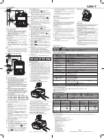
See Figure 6 for the use of power adaptor.
Using Power Adaptor
Figure 6. Using Power Adaptor
Connecting USB Interface
See Figure 7 for USB interface connection.
General Specifications
18 sets
Test Voltage
Automatically source the voltage.
Preset the timer for
two points and the Meter will carry out the measurement automatically.
B. Insulation Resistance Measurement
less


