UDP6720 Series Digital Control Power Supply
User’s Manual
20
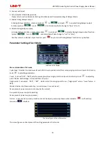
Count Configuration Table of List Mode
Table setting
:
serial number of each group is corresponding to voltage, current and time value, push rotary knob
to
set parameter;
Voltage
:
adjust the actual output voltage value
;
Current
:
adjust the current value
;
Time
:
duration output time value in this serial number
;
,
: operating status at the current, push rotary knob
to switch mode
;
Save: save the setting parameter for powerdown function, push rotary knob
to save the current setting;
: clear parameter values in the table all to zero (voltage 00.00, current 00.00, time 00.00), push rotary knob
to eliminate the setting parameter values in the table;
Notice: clear select function is eliminate the corresponding group of origin point to count.
Parameter Setting of Delayer Mode
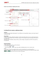
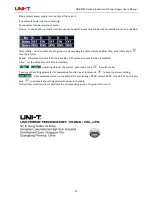
Interface of Delayer Mode
It presents power output status and delayer time of user configuration
,
it’s convenient to view the data.
Protection setting
:
this function can set protection value of voltage, current and power, push rotary knob
select
“√”
to turn on protection function
;
Cycle index
:
It divide into maximum inf and 1-999. A cycle period is start form setup origin point to end point;
Count
:
It can set “001” - “048”, which is excute group from origin point to end point. Push rotary knob
to
adjusting parameter;
Origin point: It can adjust
“
000
”
-
“
047
”
, which is start from origin point to run. Push rotary knob
to adjusting
parameter (“origin point” value + “count” value
≤
048)
Mode: It divide into three mode stop, run and pasue, it can not set
;

